13
3Housing fan
4I/O connectors (color-coded)
5Expansion slots
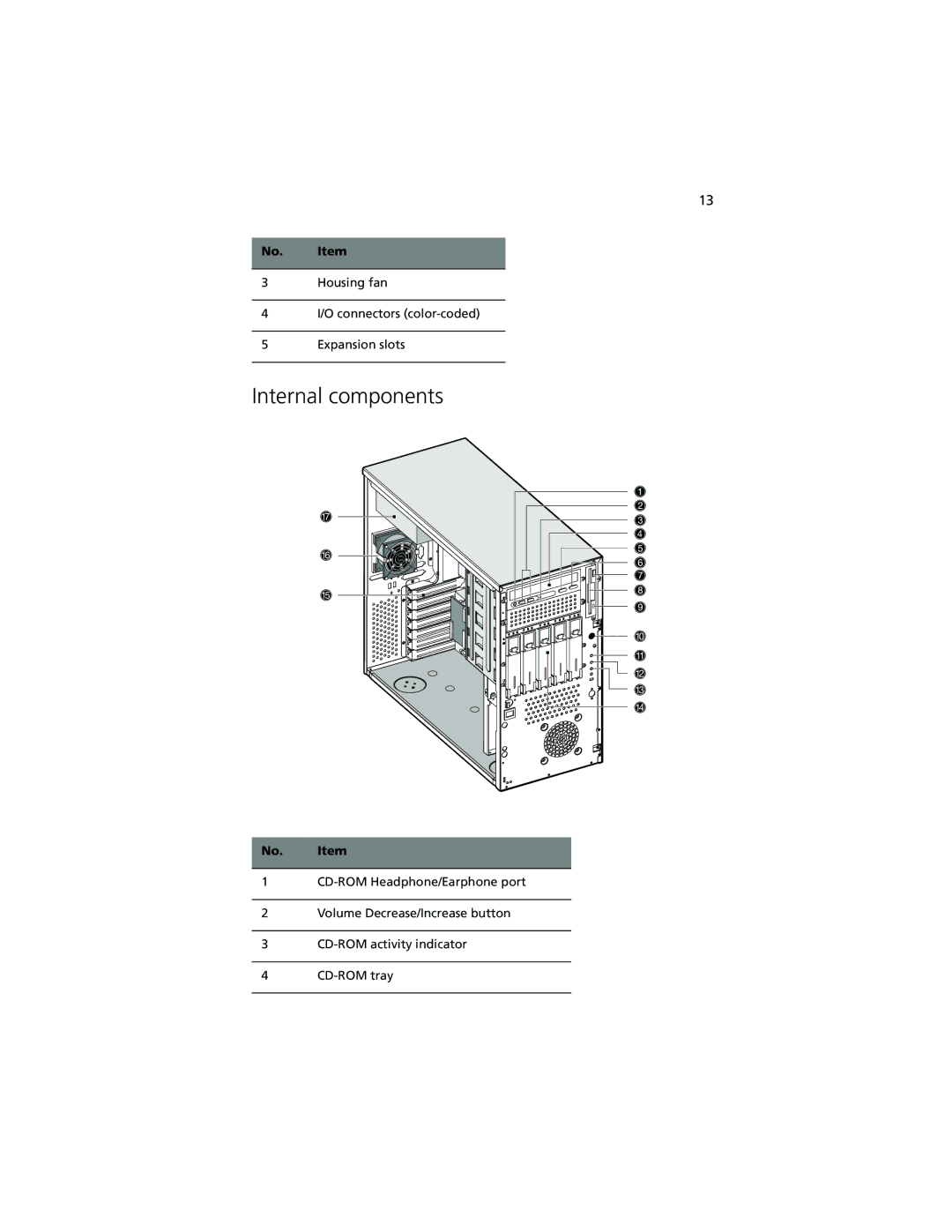
No.
Item
1
CD-ROM Headphone/Earphone port
2
Volume Decrease/Increase button
3
CD-ROM activity indicator
4
CD-ROM tray