59
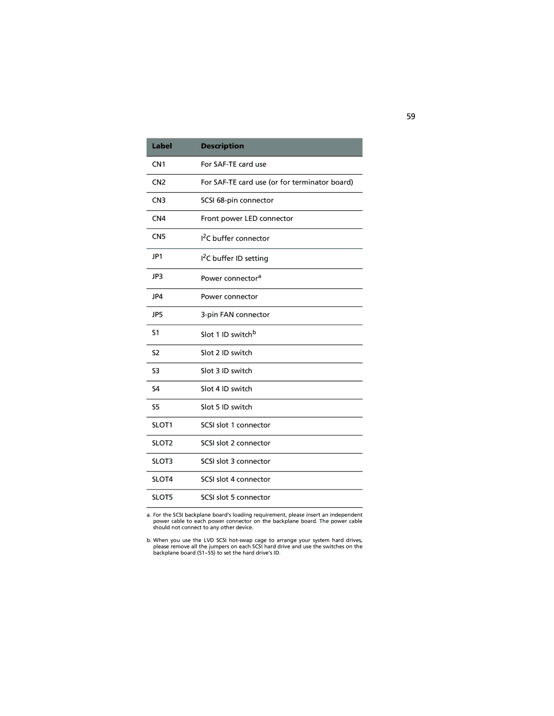
Label | Description |
|
|
CN1 | For |
|
|
CN2 | For |
|
|
CN3 | SCSI |
|
|
CN4 | Front power LED connector |
|
|
CN5 | I2C buffer connector |
|
|
JP1 | I2C buffer ID setting |
|
|
JP3 | Power connectora |
|
|
JP4 | Power connector |
|
|
JP5 | |
|
|
S1 | Slot 1 ID switchb |
|
|
S2 | Slot 2 ID switch |
|
|
S3 | Slot 3 ID switch |
|
|
S4 | Slot 4 ID switch |
|
|
S5 | Slot 5 ID switch |
|
|
SLOT1 | SCSI slot 1 connector |
|
|
SLOT2 | SCSI slot 2 connector |
|
|
SLOT3 | SCSI slot 3 connector |
|
|
SLOT4 | SCSI slot 4 connector |
|
|
SLOT5 | SCSI slot 5 connector |
a. For the SCSI backplane board's loading requirement, please insert an independent power cable to each power connector on the backplane board. The power cable should not connect to any other device.
b. When you use the LVD SCSI
