32 | 2 System tour |
The distance from the center of two holes with closer spacing to the center of the next pair is equivalent to 1U.
When installing components, you must start your measurement from the center of the two holes with closer spacing. Otherwise, the screw holes on the component may not match those on the rack.
Screw types used
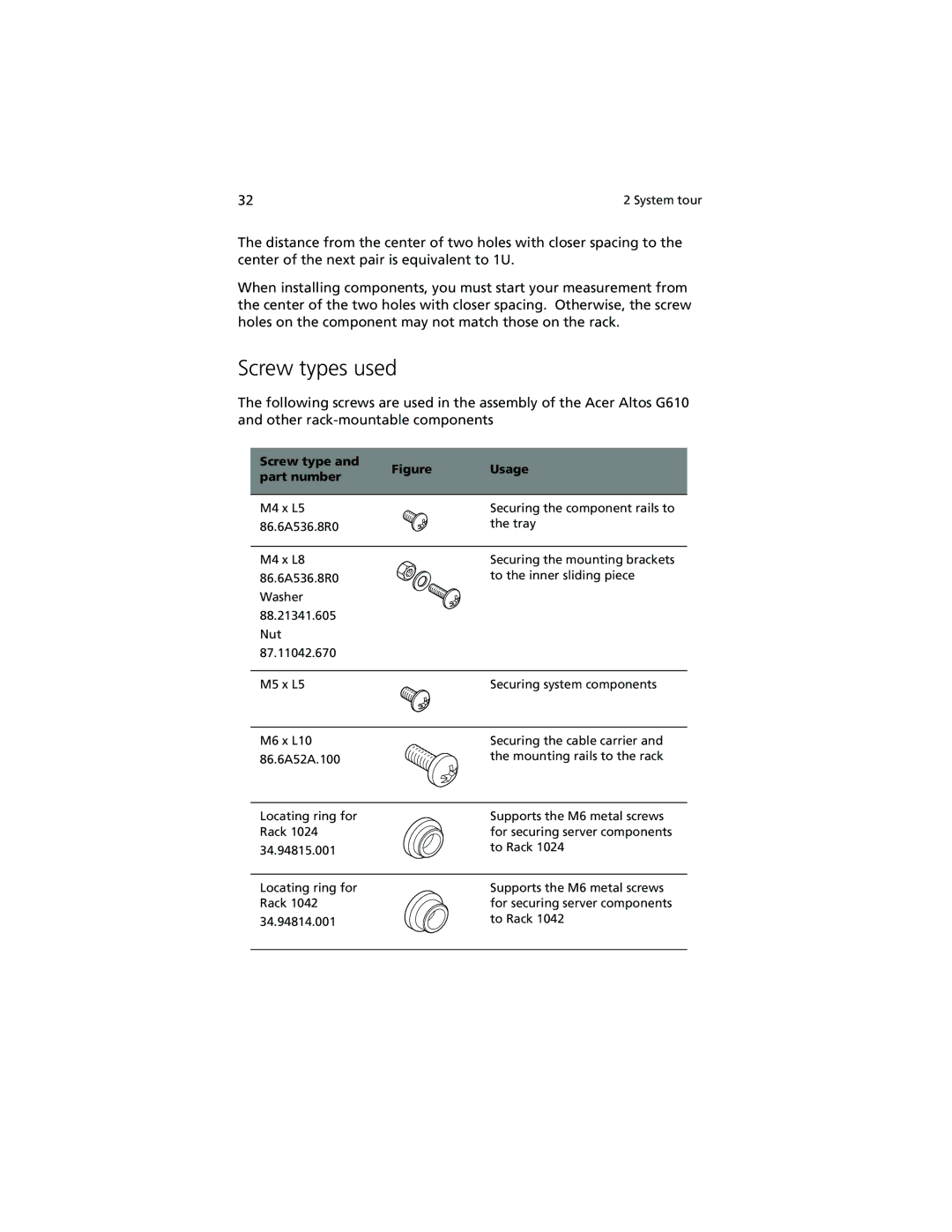
The following screws are used in the assembly of the Acer Altos G610 and other
Screw type and | Figure | Usage | |
part number | |||
|
| ||
M4 x L5 |
| Securing the component rails to | |
86.6A536.8R0 |
| the tray | |
M4 x L8 |
| Securing the mounting brackets | |
86.6A536.8R0 |
| to the inner sliding piece | |
Washer |
|
| |
88.21341.605 |
|
| |
Nut |
|
| |
87.11042.670 |
|
| |
M5 x L5 |
| Securing system components | |
M6 x L10 |
| Securing the cable carrier and | |
86.6A52A.100 |
| the mounting rails to the rack |
Locating ring for Rack 1024
34.94815.001
Supports the M6 metal screws for securing server components to Rack 1024
Locating ring for Rack 1042 34.94814.001
Supports the M6 metal screws for securing server components to Rack 1042