Chapter 2. Installation
SW 2: Off (up)
On (down)
=Factory Default
=Normal (previous settings saved)
If dip switch 2 is set to the Off (up) position, the unit continues to use the factory default settings until Switch 2 is set to the On (down) position. Also, area code, phone numbers, SPIDS, and stored numbers are cleared.
|
|
| OFF |
|
|
|
|
|
|
|
|
| ON | 1 | 2 | 3 | 4 |
|
|
POWER | RS232 | MODEM |
|
|
|
| 2 | 1 | ISDNU |
OFF 
ON
1 2 3 4
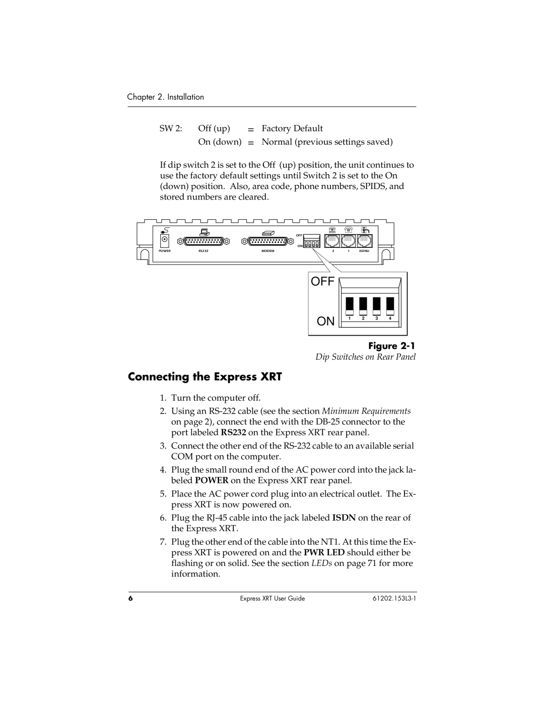
Figure
Dip Switches on Rear Panel
Connecting the Express XRT
1.Turn the computer off.
2.Using an
3.Connect the other end of the
4.Plug the small round end of the AC power cord into the jack la- beled POWER on the Express XRT rear panel.
5.Place the AC power cord plug into an electrical outlet. The Ex- press XRT is now powered on.
6.Plug the
7.Plug the other end of the cable into the NT1. At this time the Ex- press XRT is powered on and the PWR LED should either be flashing or on solid. See the section LEDs on page 71 for more information.
6 | Express XRT User Guide |