Programming Guide
Safety Guidelines
Printing History
Table of Contents
Language Dictionary
Internally Triggered Measurements
Output Commands
Compatibility Language
Error Messages
Scpi Conformance Information
Example Programs
About this Guide
Documentation Summary
External References
Gpib References
Scpi References
Supported Applications
VXIplug&play Power Products Instrument Drivers
Downloading and Installing the Driver
System Requirements
RS-232 Capabilities of the DC Source
Accessing Online Help
Gpib Capabilities of the DC Source
Gpib Address
RS-232 Flow Control
RS-232 Programming Example
Baud Rate
Conventions Used in This Guide
RS-232 Troubleshooting
Introduction to Scpi
Boldface font
Types of Scpi Commands
Multiple Commands in a Message
Types of Scpi Messages
Including Common Commands
Using Queries
Moving Among Subsystems
Headers
Query Indicator
Message Unit
Message Unit Separator
Suffixes and Multipliers
Scpi Data Formats
Numerical Data Formats
Response Data Types
Scpi Command Completion
Using Device Clear
Page
Programming the Output
Power-on Initialization
Introduction
Enabling the Output
Maximum Voltage
Output Voltage
Output Current
Maximum Current
Scpi Triggering Nomenclature
Setting the Voltage or Current Trigger Levels
Triggering Output Changes
Output Trigger System Model
Initiating the Output Trigger System
Generating Triggers
Making Measurements
Voltage and Current Measurements
DC Measurements
RMS Measurements Agilent 66312A, 66332A Only
Current Ranges
Internally Triggered Measurements
Measurement Trigger System Model
Sequence Form Alias SEQuence2 ACQuire
Generating Measurement Triggers Agilent 66312A, 66332A Only
BUS
Trigger Commands Used to Measure Output Pulses
Measuring Output Pulses Agilent 66312A, 66332A Only
Current Detector
Pulse Measurement Queries
Controlling Measurement Samples
Varying the Voltage or Current Sampling Rate
Multiple Measurements Agilent 66312A, 66332A Only
Pulse Measurement Example Agilent 66312A, 66332A only
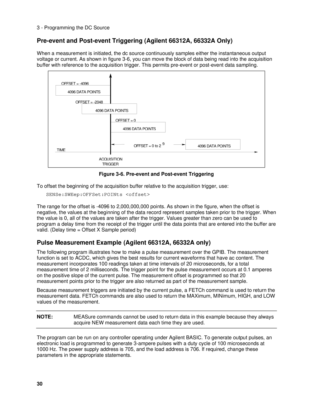
Pre-event and Post-event Triggering
Option Base
Power-On Conditions
Programming the Status Registers
Operation Status Group
Questionable Status Group
Standard Event Status Group
Status Byte Register
MSS Bit
Determining the Cause of a Service Interrupt
Servicing Operation Status and Questionable Status Events
RQS Bit
Discrete Fault Indicator DFI
Inhibit/Fault Indicator
Monitoring Both Phases of a Status Transition
Remote Inhibit RI
DFI Programming Example
Using the Inhibit/Fault Port as a Digital I/O
Bit Weight
Pin
Page
Subsystem Commands
Language Dictionary
Subsystem Commands Syntax
DFI
ALC
Subsystem Commands Syntax
Programming Parameters
Common Commands
Common Commands Syntax
Output Programming Parameters
CALibrateCURRentNEGative
Calibration Commands
CALibrateCURRent
CALibrateCURRentMEASureLOWRange
CALibrateDATA
CALibratePASSword
Command Syntax CALibrateSAVE Parameters None Examples
CALibrateLEVel
CALibrateVOLTagePROTection
CALibrateSTATe
CALibrateVOLTage
Query Syntax CALibrateSTATe?
MEASureARRayVOLTage? FETChARRayVOLTage?
Measurement Commands
MEASureARRayCURRent? FETChARRayCURRent?
Query Syntax
MEASureCURRentHIGH? FETChCURRentHIGH?
MEASureCURRent? FETChCURRent?
MEASureCURRentACDC? FETChCURRentACDC?
FETChCURRent? applies to Agilent 66312A, 66332A Only
MEASureCURRentLOW? FETChCURRentLOW?
MEASureCURRentMAXimum? FETChCURRent MAXimum?
MEASureCURRentMINimum? FETChCURRentMINimum?
MEASureVOLTageHIGH? FETChVOLTageHIGH?
MEASureVOLTage? FETChVOLTage?
MEASureVOLTageACDC? FETChVOLTageACDC?
FETChVOLTage? applies to Agilent 66312A, 66332A Only
MEASureVOLTageLOW? FETChVOLTageLOW?
MEASureVOLTageMAXimum? FETChVOLTageMAXimum?
MEASureVOLTageMINimum? FETChVOLTageMINimum?
Unit a amperes *RST Value MAX high range
SENSeCURRentRANGe
SENSeCURRentDETector
Returned Parameters NR3
SENSeSWEepPOINts
SENSeFUNCtion
SENSeSWEepOFFSetPOINts
SENSeSWEepTINTerval
RECTangular
SENSeWINDow
HANNing
Returned Parameters CRD
OUTPutDFI
Output Commands
OUTPut
OUTPutDFISOURce
OUTPutPROTectionDELay
OUTPutPONSTATe
OUTPutPROTectionCLEar
OUTPutRIMODE
OUTPutRELay
OUTPutRELayPOLarity
Query Syntax OUTPputRELayPOLarity?
SOURceCURRentTRIGger
Default Suffix
SOURceCURRent
SOURceCURRentPROTectionSTATe
SOURceVOLTage
SOURceDIGitalDATA
SOURceDIGitalFUNCtion
Query Syntax SOURceDIGitalDATA?
SOURceVOLTagePROTection
SOURceVOLTageALCBANDwidth? SOURceVOLTageALCBWIDth?
SOURceVOLTageTRIGger
Agilent 66332A, 6631B, 6632B, 6633B and 6634B Only
STATusOPERation?
Status Commands
STATusPRESet
STATusOPERationCONDition?
Parameters Preset Value
STATusOPERationENABle
Query Syntax STATusOPERationENABle?
STATusOPERationNTR STATusOPERationPTR
STATusQUEStionableENABle
STATusQUEStionable?
STATusQUEStionableCONDition?
CLS
Command Syntax *CLS Parameters None
STATusQUEStionableNTR STATusQUEStionablePTR
STATQUESNTR?STATQUESPTR?
ESR?
Bit Configuration of Standard Event Status Enable Register
ESE
OPC
PSC on
PSC
SRE
Example
WAI
Bit Configuration of Status Byte Register
STB?
NR1 register binary value
DISPlayMODE
System Commands
DISPlay
DISPlayTEXT
SYSTemVERSion?
SYSTemERRor?
SYSTemLANGuage
Parameters none Returned Parameters NR2
SYSTemRWLock
SYSTemLOCal
SYSTemREMote
IDN?
RCL
Command Syntax RCL NRf Parameters Example
OPT?
RST
SAV
RST Settings
Command Syntax SAV NRf Parameters Example
TST?
INITiateSEQuence INITiateNAME
Trigger Commands
ABORt
INITiateCONTinuousSEQuence1 INITiateCONTinuousNAME
TRIGgerSEQuence2 TRIGgerACQuire
TRIGger
TRIGgerSOURce
Abor Currtrig Init *TRG Volttrig
Parameters RST Value Examples
TRIGgerSEQuence2COUNtCURRent TRIGgerACQuireCOUNtCURRent
TRIGgerSEQuence2COUNtVOLTage TRIGgerACQuireCOUNtVOLTage
TRIGSEQ2COUNCURR 5 Trigacqcouncurr
TRIGSEQ2HYSTVOLT TRIGSEQ2LEVCURR
TRIGSEQ2HYSTCURR TRIGSEQ2LEVVOLT
TRIGSEQ2LEVVOLT TRIGSEQ2HYSTCURR
TRIGgerSEQuence2LEVelCURRent TRIGgerACQuireLEVelCURRent
TRIGgerSEQuence2LEVelVOLTage TRIGgerACQuireLEVelVOLTage
TRIGSEQ2LEVCURR TRIGSEQ2HYSTVOLT
TRIGgerSEQuence2SLOPeCURRent TRIGgerACQuireSLOPeCURRent
TRIGgerSEQuence2SLOPeVOLTage TRIGgerACQuireSLOPeVOLTage
TRIGSEQ2SLOPVOLT
TRIGgerSEQuence1DEFine TRIGgerSEQuence2DEFine
Parameters None Related Commands
TRIGgerSEQuence2SOURce TRIGgerACQuireSOURce
TRG
Page
Scpi Confirmed Commands
Non-SCPI Commands
Scpi Version
Page
Table B-1. COMPatibility Power-on Settings Command
Command Setting
Similar Scpi Command
Table B-2. COMPatibility Commands Compatibility
ERR? FAULT? ID? IOUT?
ASTS? CLR
Compatibility Command
Table B-2. COMPatibility Commands Description Similar Scpi
These commands determine the conditions that will set bits
Table B-2. COMPatibility Commands
Compatibility Description Command
Error
Norm Fast INH ERR UNR +CC
RQS ERR RDY
FAU
Page
Error Number List
Bit Set Error Number Error Code Error Type
Table C-1. Error Numbers
Error Number
Page
Agilent 82335A Driver
Assigning the Gpib Address in Programs
Types of DOS Drivers
National Instruments Gpib Driver
Error Handling
Basic Controllers
Example Programs D
Example 2. IBM Controller Using National Interface
Call IBCLRPS%
CODES$=*CLS
Example 3. Controller Using Basic
Option Base
Index
Index
100
101
Scpi
102
Manual Updates