3URJUDPPLQJ*XLGH
Warranty
6DIHW\6XPPDU\
2127235$7,1$13/26,9$70263+5
2WKHU6DIHW\,QIRUPDWLRQ
DUQLQJVDQG&DXWLRQV
6DIHW\6\PEROV
$ERXW7KLV0DQXDO
6HUYLFHDQG6XSSRUW
Page
Using the Attenuator
Setting Up the Hardware Setting Up the Attenuation
Example, Setting the Calibration
Configuring the Hardware
Configuring the Hardware Setting Up the Software
Example, Setting a Return Loss
Setting the Gpib Address
Automatic Sweep
Selecting the Through-Power Mode
Setting the Display Brightness
Selecting the Setting used at Power-On
Selecting the Shutter State at Power On
Units Command Summary Common Commands
Some Notes about Programming and Syntax Diagram
Conventions
DISPlay Commands 104
INPut Commands 106
OUTPut Commands 110
STATus Commands 114
User Calibration Commands 123
Switching on the Attenuator 149
Temperature 148 Humidity Instrument Positioning and Cooling
Operating and Storage Environment 148
Definition of Terms 165 Specifications 167
Other Specifications 171 Declaration of Conformity 172
Monitor Output 149 Optical Output 150
Gpib Interface 150
Polarization Dependent Loss PDL Optional
Preserving Connectors 256
Polarization Dependant Loss Test Mueller method 192
How to clean connectors 258
How to clean connector adapters 259
How to clean connector interfaces 260
How to clean bare fiber adapters 261
How to clean instruments with a recessed lens inter
How to clean optical devices which are sensitive to me
How to clean metal filters or attenuator gratings
Additional Cleaning Information 268
276
Table of Contents
List of Figures
Figure D-6
List of Tables
List of Tables
Getting Started
Getting Started
Using the Attenuator
Using the Modify Keys
Using the Attenuator
Attenuator Keys
Making an Automatic Sweep
Making an Attenuation Sweep
Making an Attenuation Sweep
Manual Sweep
Manual Sweep
Parameters for an Automatic Sweep
Using your Attenuator as a Variable Back Reflector
Using your Attenuator as a Variable Back
Reflector
Using the Through-Power Mode
Using the Through-Power Mode
Selecting the Wavelength Calibration and Its Function
Selecting the Wavelength Calibration and Its Function
Using the Attenuator
Using the Attenuator
Setting Up the Hardware
Setting Up the Hardware
Setting Up the Attenuation
Setting Up the Attenuation
Entering the Attenuation Factor
Attenuation Factor on the Display
Resetting the Attenuation Factor
Entering a Calibration Factor
Calibration Factor on the Display
Editing the Calibration Factor
Entering the Wavelength
Resetting the Wavelength
Wavelength on the Display
Example, Setting the Calibration
Example, Setting the Calibration
Hardware Configuration for Attenuation Example a
Hardware Configuration for Attenuation Example B
Power of the source
Warmup. The multimeter needs around 20 minutes to warmup.
Example, Setting the Calibration
Making an Attenuation Sweep
Making an Attenuation Sweep
Configuring the Hardware
Configuring the Hardware
Automatic Sweep
Setting Up an Automatic Sweep
Automatic Sweep
Editing the Parameters
Starting the Setting Up
Selecting the Automatic Sweep Application
Resetting the Parameters
Executing the Automatic Sweep
Setting Up a Manual Sweep
Repeating the Sweep
Restarting the Sweep
Running the Automatic Sweep
Editing the Stop Parameter
Executing the Manual Sweep
Running the Manual Sweep
Resetting, or store their setting for later recall
Example, an Automatic Attenuation Sweep
Changing the Attenuation in a Manual Sweep
Example, an Automatic Attenuation Sweep
Example, an Automatic Attenuation Sweep
Example, an Automatic Attenuation Sweep
Using your Attenuator as a Variable Back Reflector
Using your Attenuator as a Variable Back Reflector
Using your Attenuator as a Variable Back Reflector
Editing the Setup
Setting Up the Software
Setting Up the Software
Executing the Back Reflector Application
Editing the Value for the Reference Return Loss
Example, Setting a Return Loss
Example, Setting a Return Loss
Hardware Configuration for Variable Return Loss
Example, Setting a Return Loss
Setting Up the System
Setting Up the System
Resetting the Gpib Address
Setting the Gpib Address
Setting the Gpib Address
Resetting the Function of the Wavelength Calibration Data
Setting the Function of the Wavelength Calibration
Lambdcal Indicator on the Display
Resetting the Wavelength Calibration Data Set
If you are using the instrument in an environment where
Temperature changes, you should not use the user wavelength
Usercal Indicator on the Display
Selecting the Through-Power Mode
Selecting the Through-Power Mode
Display in Through-Power Mode
Setting the Display Brightness
Deselecting the Through-Power Mode
Resetting the Through-Power Mode
Resetting the Display Brightness
Selecting the Setting used at Power-On
Resetting the Power-On Setting
Selecting the Setting used at Power-On
Locking Out ENB/DIS
Selecting the Shutter State at Power On
Resetting the ENB/DIS Lock Out
Resetting the Shutter State at Power On
Selecting the Shutter State at Power On
Resetting the Display Resolution
Setting the Display Resolution
Setting the Display Resolution
Storing and Recalling Settings
Storing and Recalling Settings
Storing the Setting
Recalling a Setting
Resetting the Instrument
Recalling a User Setting
Recalling a Setting
Programming the Attenuator
Programming Attenuator
Gpib Interface
Gpib Interface
Gpib Capabilities Mnemonic Function
AH1
How the Attenuator Receives and Transmits Messages
Returning the Instrument to Local Control
How the Input Queue Works
Error Queue
Clearing the Input Queue
Output Queue
How the Attenuator Receives and Transmits Messages
Some Notes about Programming and Syntax Diagram Conventions
Some Notes about Programming and Syntax Diagram Conventions
Short Form and Long Form
Command and Query Syntax
String
Value
Wsp
Remote Commands
Remote Commands
Command Summary
Units and Allowed Mnemonics Default
Common Command Summary
Units
Command Summary
Command List
ValueMINDE DB
Value 32768 32767
Common Commands
Common Commands
Common Status Information
SRQ, The Service Request
Common Status Registers
Syntax
Definition
Event Status Enable Register
Example
Standard Event Status Register
Bits Mnemonics BIT Value
OPC
RCL
Reset State Default Setting Parameter Reset Value
SAV
Service Request Enable Register
SRE
No T EBit 6 cannot be masked
Status Byte Register
TST?
Self Test Results
DISPlay Commands
DISPlay Commands
DISPlayBRIGhtness
DISPlayBRIGhtness?
DISPlayENABle?
DISPlayENABle
Description
INPut Commands
INPut Commands
INPutATTenuation
INPutATTenuation?
INPutLCMode?
INPutLCMode
INPutOFFSet
INPutOFFSet?
INPutOFFSetDISPlay
INPutWAVelength
OUTPut Commands
OUTPut Commands
INPutWAVelength?
OUTPutAPMode
Using any of the INPutATTenuation commands or queries, or
Any of the INPutOFFSet commands or queries, switches
Absolute power mode off automatically
OUTPutAPMode?
OUTPutPOWer
OUTPutSTATe
OUTPutPOWer?
OUTPutSTATe?
STATus Commands
OUTPutSTATeAPOWeron
OUTPutSTATeAPOWeron?
STATus Commands
STATus Commands
STATusOPERationCONDition?
Status Registers
STATusOPERationENABle?
STATusOPERationENABle
STATusOPERationEVENt?
STATusOPERationNTRansition?
STATusOPERationNTRansition
STATusOPERationPTRansition
STATusOPERationPTRansition?
STATusQUEStionableENABle
STATusQUEStionableCONDition?
STATusQUEStionableEVENt?
STATusQUEStionableENABle?
STATusQUEStionableNTRansition
STATusQUEStionablePTRansition
STATusQUEStionableNTRansition?
STATusQUEStionablePTRansition?
SYSTem Commands
STATusPRESet
SYSTemERRor?
SYSTem Commands
User Calibration Commands
User Calibration Commands
Entering the User Calibration Data
Power = -Power
UCALibrationSTARt
UCALibrationSTARt?
UCALibrationSTATe
UCALibrationSTOP
UCALibrationSTATe?
UCALibrationVALue
UCALibrationVALue?
128
Programming Examples
Programming Examples
Example 1 Checking Communication
Function
Listing
Example 1 Checking Communication
Example 2 Status Registers and Queues
Example 2 Status Registers and Queues
133
134
Setting Up the Equipment
Example 3 Measuring and Including the Insertion Loss
Requirements
Example 3 Measuring and Including the Insertion Loss
Include the attenuator
137
138
Example 4 Running an Attenuation Sweep
Example 4 Running an Attenuation Sweep
140
Installation
Installation
Safety Considerations
Safety Considerations
Initial Inspection
Line Power Cable
AC Line Power Supply Requirements
AC Line Power Supply Requirements
Figure A-2 Rear Panel Markings
Replacing the Battery
Replacing the Fuse
Figure A-3 Releasing the Fuse Holder
Temperature
Operating and Storage Environment
Humidity
Instrument Positioning and Cooling
Switching on the Attenuator
Switching on the Attenuator
Monitor Output
Disabling the Optical Output
Optical Output
Optical Output
Connector
Figure A-6
Claims and Repackaging
Gpib Logic Levels
Return Shipments to Agilent Technologies
Claims and Repackaging
Claims and Repackaging
154
Accessories
Accessories
Instrument and Options
Gpib Cables and Adapters
Instrument and Options
Table B-1 Mainframe Description Model No
Straight Contact Connector
Connector Interfaces and Other Accessories
Connector Interfaces and Other Accessories
Accessories
Option 201, Angled Contact Connector
Figure B-2 Angled Contact Connector Configuration
Table B-3 Connector Interface Description AgilentModel No
162
Specifications
Specifications
Definition of Terms
Definition of Terms
Repeatability
Polarization mode dispersion
Return loss
Specifications
Specifications
Table C-2 Monitor Output Options
Monitor Output typ
Operating Modes
Supplementary Performance Characteristics
Table C-3 Multimode Options Wavelength Range
General
Environmental
Other Specifications
Power
Other Specifications
Acoustic Noise Emission Geräuschemissionswerte
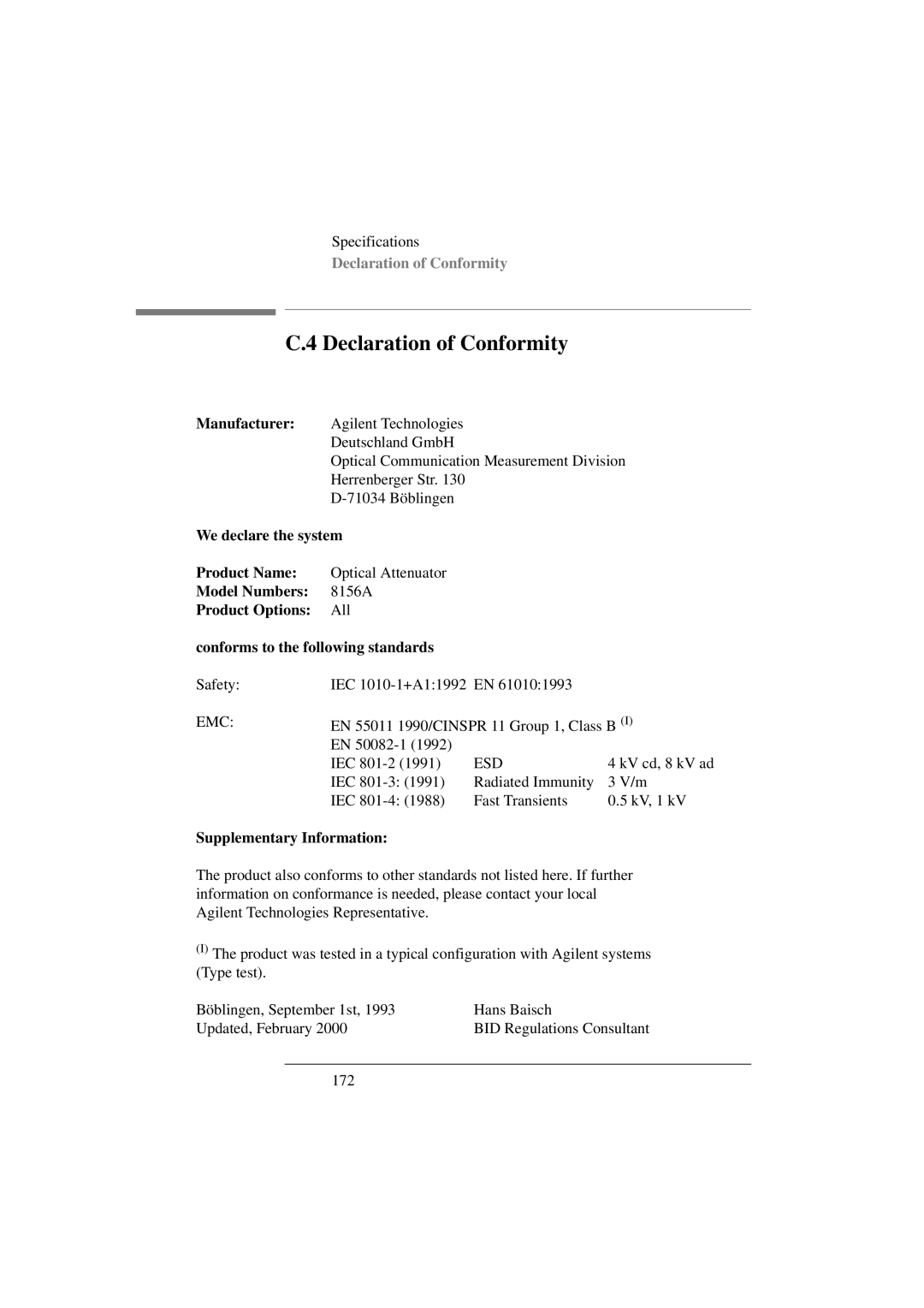
Declaration of Conformity
Declaration of Conformity
Performance Tests
Performance Tests
Equipment Required
Equipment Required
176
Instrument Specification
Test Record
Test Failure
Test Record
Performance Test
Performance Test
Total Insertion Loss Test
Specifications
Typ
Figure D-2 Total Insertion Loss Test Setup 1, Options 201
Figure D-3 Total Insertion Loss Test Setup 1, Option
Figure D-5 Total Insertion Loss Test Setup 2, Options 201
Specifications Agilent 8156A
II. Linearity/Attenuation Accuracy Test
To 0.00 dB
Measurement to prevent changes of state of polarization
III. Attenuation Repeatability Test
Figure D-7 Return Loss Test Setup 1, Options 100, 101
IV. Return Loss Test Options 100, 101,
No T E
Figure D-8 Return Loss Test Setup 2, Options 100
Options 201
Figure D-10 Return Loss Test Setup 1, Options 201
Figure D-11 Return Loss Test Setup 2, Option
Monitor output is terminated
Figure D-12 Return Loss Test Setup 2, Option
Polarization Dependent Loss PDL Optional
V. Polarization Dependent Loss PDL Optional
Table D-2 Equipment for the PDL test
Figure D-13 PDL Test Setup 1 Reference Measurement
Polarization Dependant Loss Test Mueller method
Isolator must not move during and between all measurements
Until these are finished
Set plates for Linear Horizontal polarization
Polarization Dependent Loss PDL Optional
Linear vertical Linear diagonal RH circular
Measure the Reference Power
Polarization
Polarization Dependent Loss PDL Optional
Set the 8156A Attenuator DUT to 0dB using the modify keys
Head must not move until the measurements are finished
Polarization Dependent Loss PDL Optional
Table D-3 Performance Test Agilent 8156A
Performance Test for the Agilent 8156A
Polarization Dependent Loss PDL Optional
Performance Test for the Agilent 8156A Option
Result
204
01dB + 0.01dB
206
207
208
Polarization Dependent Loss PDL Optional
210
211
Input 40dB
213
214
215
Polarization Dependent Loss PDL Optional
217
218
219
220
10.9dB
222
Polarization Dependent Loss PDL Optional
224
225
Input 55dB
227
228
229
Polarization Dependent Loss PDL Optional
231
232
233
234
235
236
Polarization Dependent Loss PDL Optional
238
239
01dB + 0.01dB 240
Test Facility
Special Notes
Polarization Dependent Loss Test
Mueller Coefficients
Minimum and maximum transmission
Option Wavelength 1550nm nominal
Polarization Dependent Loss PDL Optional
Cleaning Information
Cleaning Information
Cleaning Instructions for this Instrument
Why is it important to clean optical devices ?
Safety Precautions
Safety Precautions
Standard Cleaning Equipment
What do I need for proper cleaning?
What do I need for proper cleaning?
Isopropyl alcohol
Dust and shutter caps
Cotton swabs
Soft tissues
Pipe cleaner
Additional Cleaning Equipment
Compressed air
Ultrasonic bath
Microscope with a magnification range about 50X up to
Warm water and liquid soap
Polymer film
Premoistened cleaning wipes
Infrared Sensor Card
Preserving Connectors
Preserving Connectors
Making Connections
Dust Caps and Shutter Caps
Cleaning Instrument Housings
Which Cleaning Procedure should I use ?
Cleaning Instrument Housings
Light dirt
How to clean connectors
Preferred Procedure
Procedure for Stubborn Dirt
How to clean connectors
An Alternative Procedure
How to clean connector adapters
How to clean connector adapters
How to clean connector interfaces
How to clean connector interfaces
How to clean bare fiber adapters
How to clean bare fiber adapters
How to clean lenses
How to clean lenses
How to clean instruments with a fixed connector interface
How to clean instruments with a fixed connector interface
System
How to clean instruments with a physical contact interface
How to clean instruments with an optical glass plate
How to clean instruments with an optical glass plate
How to clean instruments with a recessed
How to clean instruments with a recessed lens interface
Agilent Technologies 81633A and 81634A Power Sensors do not
Lens interface
Preferred Procedure
Alternative Procedure
Additional Cleaning Information
How to clean metal filters or attenuator gratings
How to clean metal filters or attenuator gratings
How to clean large area lenses and mirrors
How to clean bare fiber ends
Additional Cleaning Information
Alternative Procedure a
Damage your device
It, because they can scratch and damage your device
Remains
Other Cleaning Hints
Alternative Procedure B
Lens cleaning papers
Other Cleaning Hints
Cleaning the housing and the mainframe
Error messages
Error Messages
Display Messages
Display Messages
Hexadecimal
Bits Mnemonics Value
Gpib Messages
Command header error
Header separator error
Numeric data error
Parameter not allowed
Suffix error
Character data error
Invalid character in number
Exponent too large
String data error
Block data error
Invalid character data
Character data too long
Execution Errors
Execution error
Settings lost due to rtl
Parameter error
Hardware error
Device-Specific Errors
Device-specific error
System error
Configuration memory lost
Query Errors
Query error
Save/recall memory lost
Instrument Specific Errors
Query Deadlocked
Query Unterminated after indefinite response
201
284
Symbols
Index
HP-IB
Lockout
Resolut
Thrupowr