ASSEMBLY
ASSEMBLY
JACKSHAFT BEARING SUPPORT
ASSEMBLY
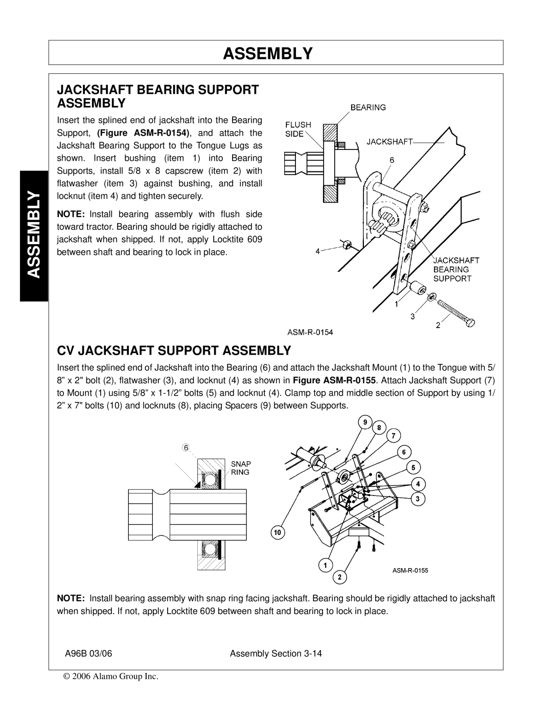
Insert the splined end of jackshaft into the Bearing Support, (Figure
NOTE: Install bearing assembly with flush side toward tractor. Bearing should be rigidly attached to jackshaft when shipped. If not, apply Locktite 609 between shaft and bearing to lock in place.
CV JACKSHAFT SUPPORT ASSEMBLY
Insert the splined end of Jackshaft into the Bearing (6) and attach the Jackshaft Mount (1) to the Tongue with 5/ 8” x 2" bolt (2), flatwasher (3), and locknut (4) as shown in Figure
NOTE: Install bearing assembly with snap ring facing jackshaft. Bearing should be rigidly attached to jackshaft when shipped. If not, apply Locktite 609 between shaft and bearing to lock in place.
A96B 03/06 | Assembly Section |
© 2006 Alamo Group Inc.