External Connection
4.8.1 EPO Principle
Diagram for Emergency Power Off (EPO) principle has to be established prior to EPO and UPS installations. Battery Breaker Box and switch gear must be installed with “shunt trip”.
Use external power supply from “Utility” and UPS output before reaching Q002, when tripping Battery Breakers and switchgear.
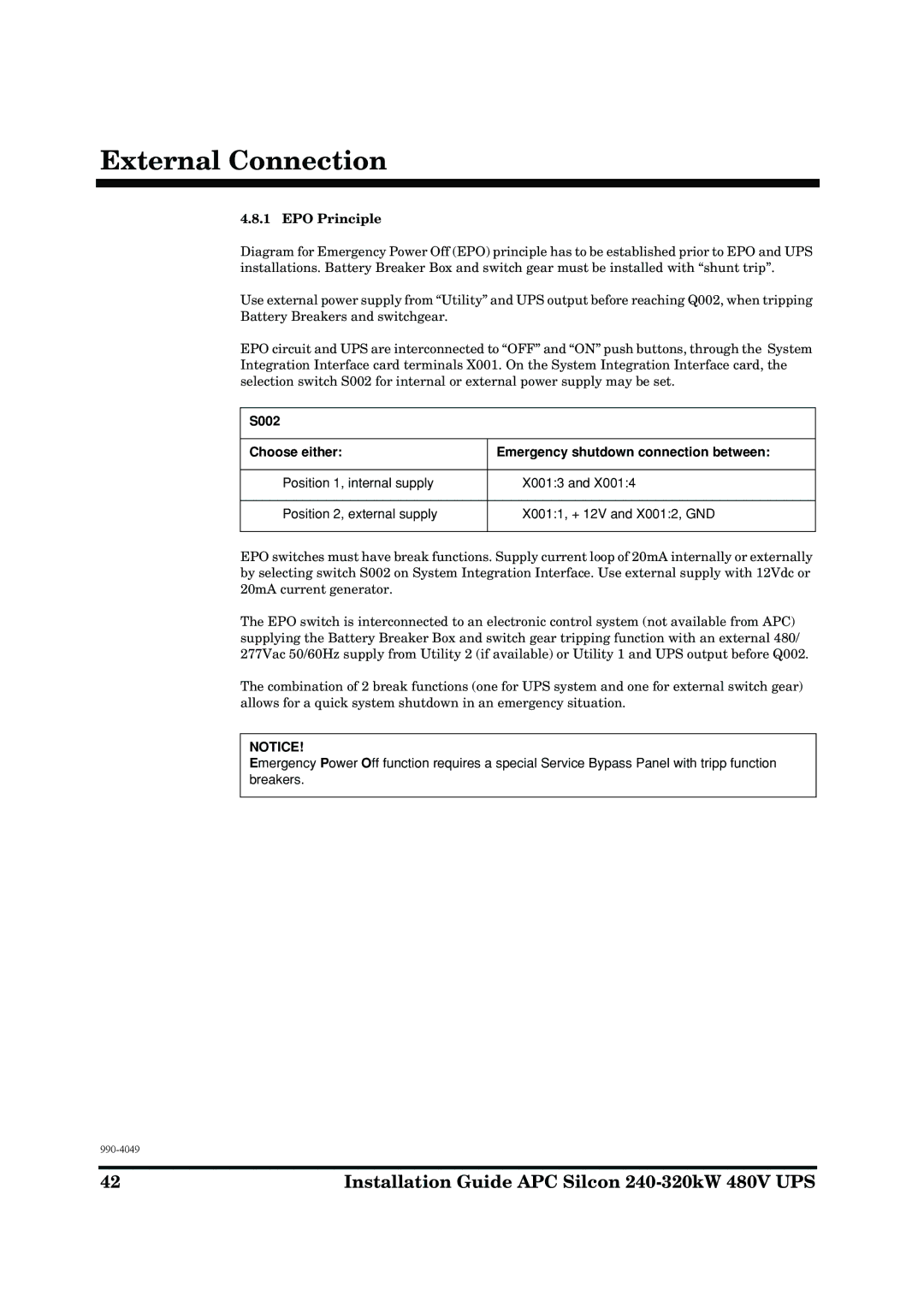
EPO circuit and UPS are interconnected to “OFF” and “ON” push buttons, through the System Integration Interface card terminals X001. On the System Integration Interface card, the selection switch S002 for internal or external power supply may be set.
S002
Choose either:
Emergency shutdown connection between:
Position 1, internal supply
X001:3 and X001:4
Position 2, external supply
X001:1, + 12V and X001:2, GND
EPO switches must have break functions. Supply current loop of 20mA internally or externally by selecting switch S002 on System Integration Interface. Use external supply with 12Vdc or 20mA current generator.
The EPO switch is interconnected to an electronic control system (not available from APC) supplying the Battery Breaker Box and switch gear tripping function with an external 480/ 277Vac 50/60Hz supply from Utility 2 (if available) or Utility 1 and UPS output before Q002.
The combination of 2 break functions (one for UPS system and one for external switch gear) allows for a quick system shutdown in an emergency situation.
NOTICE!
Emergency Power Off function requires a special Service Bypass Panel with tripp function breakers.
42 | Installation Guide APC Silcon |
