Appendix
specific Input Cable ampacities may vary from above chart.
7.Breaker/Fuse selection based on Nom input current is acceptable provided battery recharge time is short.
Consult factory for application specific assistance.
8.Grounding conductor ampacities: Refer to NEC Article
Neutral conductors ampacities: Refer to NEC Article
9.All wiring to be in accordance with all applicable national and/or local electrical codes.
10.Nominal Battery Discharge current based on full rated load, and nominal Battery voltage. 11.Maximum Battery Discharge current based on full rated load at end of Discharge.
12.Heat rejection calculated at nominal full load capacity.
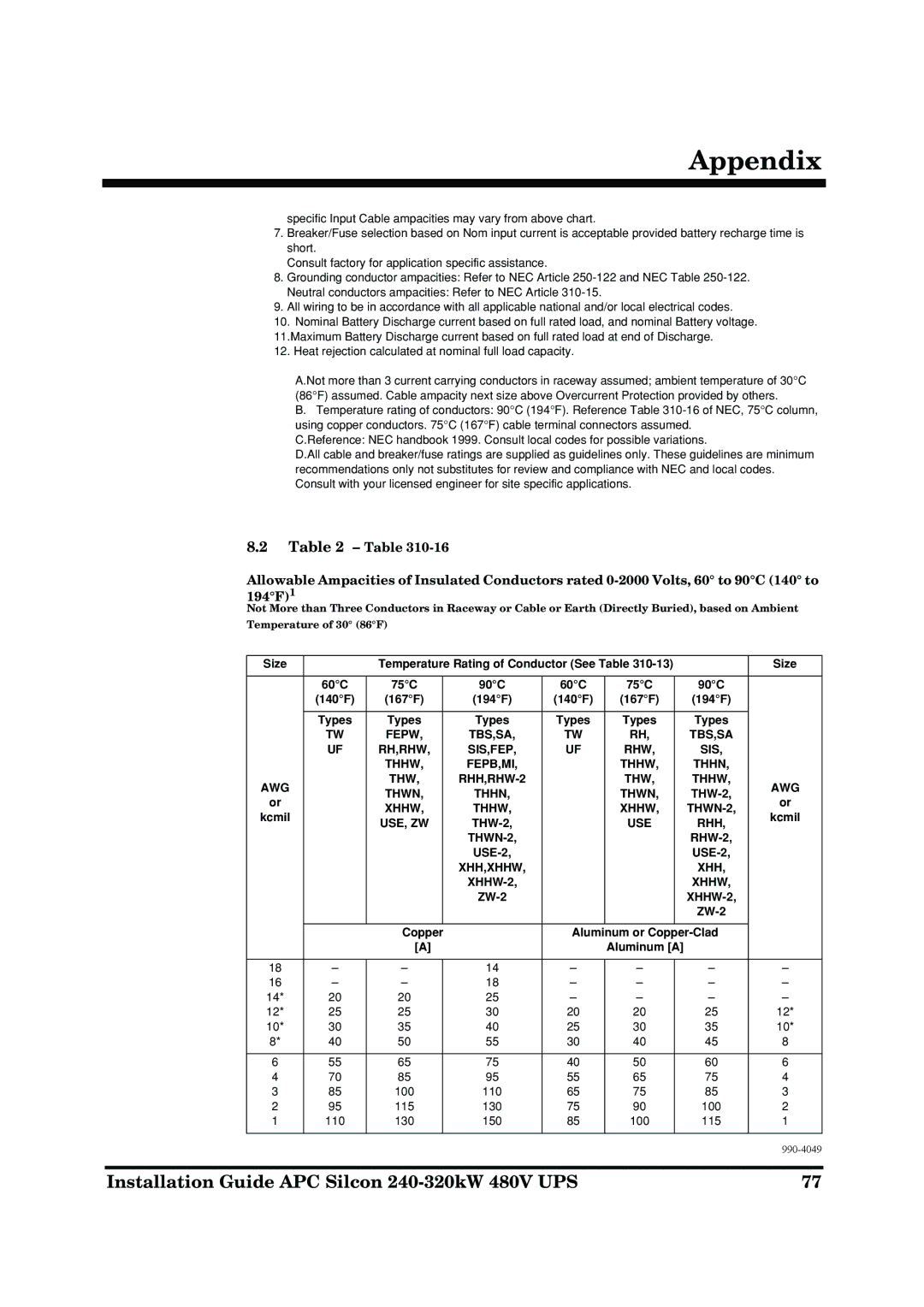
A.Not more than 3 current carrying conductors in raceway assumed; ambient temperature of 30°C (86°F) assumed. Cable ampacity next size above Overcurrent Protection provided by others.
B.Temperature rating of conductors: 90°C (194°F). Reference Table
C.Reference: NEC handbook 1999. Consult local codes for possible variations.
D.All cable and breaker/fuse ratings are supplied as guidelines only. These guidelines are minimum recommendations only not substitutes for review and compliance with NEC and local codes. Consult with your licensed engineer for site specific applications.
8.2Table 2 – Table
Allowable Ampacities of Insulated Conductors rated
Not More than Three Conductors in Raceway or Cable or Earth (Directly Buried), based on Ambient
Temperature of 30° (86°F)
Size |
| Temperature Rating of Conductor (See Table |
| Size | |||||
|
|
|
|
|
|
|
|
|
|
| 60°C | 75°C |
| 90°C | 60°C | 75°C |
| 90°C |
|
| (140°F) | (167°F) |
| (194°F) | (140°F) | (167°F) |
| (194°F) |
|
|
|
|
|
|
|
|
|
|
|
| Types | Types |
| Types | Types | Types |
| Types |
|
| TW | FEPW, |
| TBS,SA, | TW | RH, |
| TBS,SA |
|
| UF | RH,RHW, |
| SIS,FEP, | UF | RHW, |
| SIS, |
|
|
| THHW, |
| FEPB,MI, |
| THHW, |
| THHN, |
|
AWG |
| THW, |
|
| THW, |
| THHW, | AWG | |
| THWN, |
| THHN, |
| THWN, |
| |||
or |
|
|
|
| or | ||||
| XHHW, |
| THHW, |
| XHHW, |
| |||
kcmil |
|
|
|
| kcmil | ||||
| USE, ZW |
|
| USE |
| RHH, | |||
|
|
|
|
|
| ||||
|
|
|
|
|
|
|
| ||
|
|
|
|
|
|
|
| ||
|
|
|
| XHH,XHHW, |
|
|
| XHH, |
|
|
|
|
|
|
|
| XHHW, |
| |
|
|
|
|
|
|
|
| ||
|
|
|
|
|
|
|
|
| |
|
|
|
|
|
|
|
|
| |
|
| Copper |
| Aluminum or |
| ||||
|
| [A] |
|
| Aluminum [A] |
|
| ||
|
|
|
|
|
|
|
|
|
|
18 | – | – |
| 14 | – | – |
| – | – |
16 | – | – |
| 18 | – | – |
| – | – |
14* | 20 | 20 |
| 25 | – | – |
| – | – |
12* | 25 | 25 |
| 30 | 20 | 20 |
| 25 | 12* |
10* | 30 | 35 |
| 40 | 25 | 30 |
| 35 | 10* |
8* | 40 | 50 |
| 55 | 30 | 40 |
| 45 | 8 |
|
|
|
|
|
|
|
|
|
|
6 | 55 | 65 |
| 75 | 40 | 50 |
| 60 | 6 |
4 | 70 | 85 |
| 95 | 55 | 65 |
| 75 | 4 |
3 | 85 | 100 |
| 110 | 65 | 75 |
| 85 | 3 |
2 | 95 | 115 |
| 130 | 75 | 90 |
| 100 | 2 |
1 | 110 | 130 |
| 150 | 85 | 100 |
| 115 | 1 |
|
|
|
|
|
|
|
|
|
|
|
|
|
|
|
|
|
|
| |
Installation Guide APC Silcon | 77 |
