External Connection
Auxiliary contacts on the main switches transmit
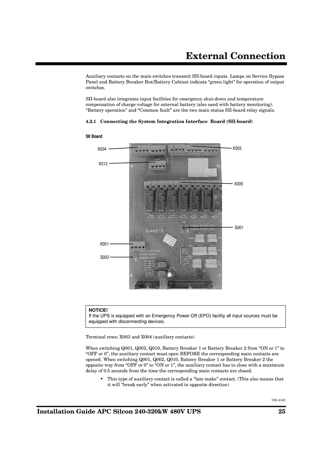
4.2.1 Connecting the System Integration Interface Board (SII-board)
SII Board
X004 ![]() X003
X003
X012
X005
S001
X001
S002
NOTICE!
If the UPS is equipped with an Emergency Power Off (EPO) facility all input sources must be equipped with disconnecting devices.
Terminal rows: X003 and X004 (auxiliary contacts)
When switching Q001, Q002, Q010, Battery Breaker 1 or Battery Breaker 2 from “ON or 1” to “OFF or 0”, the auxiliary contact must open BEFORE the corresponding main contacts are opened. When switching Q001, Q002, Q010, Battery Breaker 1 or Battery Breaker 2 the opposite way from “OFF or 0” to “ON or 1”, the auxiliary contact has to close with a maximum delay of 0.5 seconds from the time the corresponding main contacts are closed.
•This type of auxiliary contact is called a “late make” contact. (This also means that it will “break early” when activated in opposite direction)
Installation Guide APC Silcon | 25 |