American Power Conversion PD150L6F, PD150G6F manual InfraStruXure PDU, Front view

Models: PD150L6F PD150G6F

1 84
Download 84 pages 32.8 Kb
Page 14
Image 14

InfraStruXure PDU

Front view

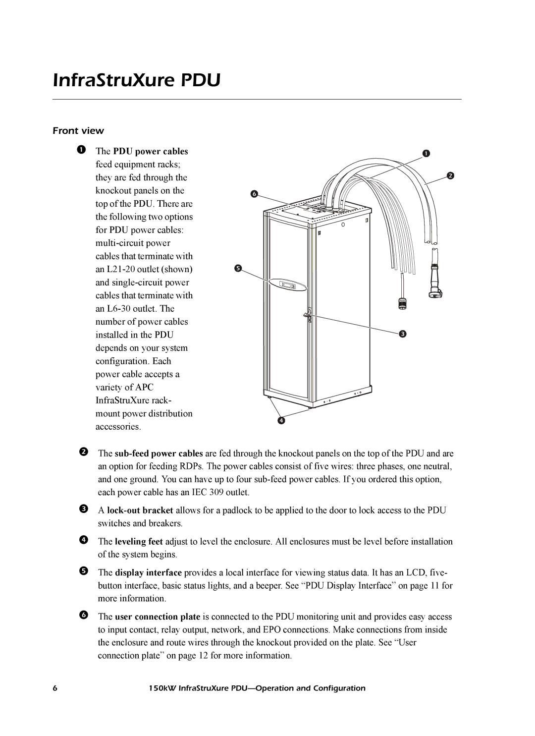
The PDU power cables feed equipment racks; they are fed through the knockout panels on the top of the PDU. There are the following two options for PDU power cables: multi-circuit power cables that terminate with an L21-20 outlet (shown) and single-circuit power cables that terminate with an L6-30 outlet. The number of power cables installed in the PDU depends on your system configuration. Each power cable accepts a variety of APC InfraStruXure rack- mount power distribution accessories.

The sub-feed power cables are fed through the knockout panels on the top of the PDU and are an option for feeding RDPs. The power cables consist of five wires: three phases, one neutral, and one ground. You can have up to four sub-feed power cables. If you ordered this option, each power cable has an IEC 309 outlet.

A lock-out bracket allows for a padlock to be applied to the door to lock access to the PDU switches and breakers.

The leveling feet adjust to level the enclosure. All enclosures must be level before installation of the system begins.

The display interface provides a local interface for viewing status data. It has an LCD, five- button interface, basic status lights, and a beeper. See “PDU Display Interface” on page 11 for more information.

The user connection plate is connected to the PDU monitoring unit and provides easy access to input contact, relay output, network, and EPO connections. Make connections from inside the enclosure and route wires through the knockout provided on the plate. See “User connection plate” on page 12 for more information.

6

150kW InfraStruXure PDU—Operation and Configuration

Page 14
Image 14
American Power Conversion PD150L6F, PD150G6F manual InfraStruXure PDU, Front view