ADVANCED MICRO SYSTEMS, INC. | HARDWARE |
After Sign-on
Enter X<CR>
The parameters are displayed. The last characters displayed will be “n= “ followed by the axis “name” character, usually “A.” To change the name:
1.Turn off power, allow discharge.
2.Turn on power.
3.Depress the desired “name” key, for instance “B.”
4.Depress the SPACE BAR. The
5.Enter X<CR>. The new name “B” is displayed.
6.Issue the S<CR> (save command). The name is stored in memory.
7.Depress
8.Enter X<CR> to
Connect the Motor
Set the motor current off (especially if your motor is small and low current model) using the “Y” command. “Y 0”<CR> (windings off)
“S”<CR> (store settings in NV memory)
Turn off the power and allow plenty of time to discharge any capacitor. Use voltmeter if necessary.
Phase | J5 Pin | Signal |
|
|
|
1A | 6 | Winding 1 |
1B | 5 | Winding 1 |
2A | 4 | Winding 2 |
2B | 3 | Winding 2 |
Before plugging into J5, insure (using a ohm meter), that there is a low resistance from pin 5 to 6, and a similar resistance between pins 3 and 4. There should NOT be a low resistance between pins 4 and 5.
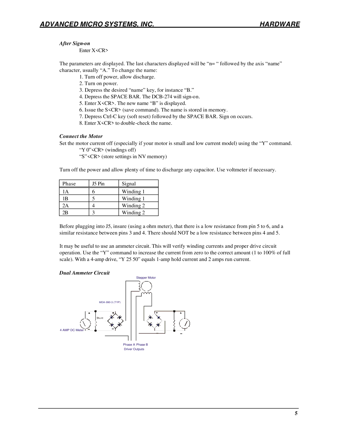
It may be useful to use an ammeter circuit. This will verify winding currents and proper drive circuit operation. Use the “Y” command to increase the current from zero to the correct amount (1 to 100% of full scale). With a
Dual Ammeter Circuit
Stepper Motor
| |
| Shunt |
4 AMP DC Meter - | - |
Phase A Phase B
Driver Outputs
- | - |
5