ADVANCED MICRO SYSTEMS, INC. | SERIAL INTERFACE |
Axis Name Assignment
Whenever the application is controlled via a “host” computer the proper protocol (handshake) MUST be used. Either the programmer must write the necessary serial, echoed
In any case a unique name must be assigned and stored in the NV memory. EVEN A SINGLE, ONE AXIS
SYSTEM REQUIRES PARTY LINE OR DAISY CHAIN PROTOCOL.
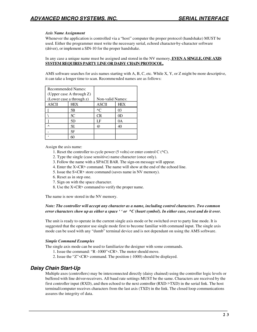
AMS software searches for axis names starting with A, B, C, etc. While X, Y, or Z might be more descriptive, it can take a longer time to scan. Recommended names are as follows:
Recommended Names: |
|
| |
(Upper case A through Z) |
|
| |
(Lower case a through z) | |||
ASCII | HEX | ASCII | HEX |
|
|
|
|
[ | 5B | ^C | 03 |
\ | 5C | CR | 0D |
] | 5D | LF | 0A |
^ | 5E | @ | 40 |
- | 5F |
|
|
‘ | 60 |
|
|
Assign the axis name:
1.Reset the controller to cycle power (5 volts) or enter control C (^C).
2.Type the single (case sensitive) name character (once only).
3.Follow the name with a SPACE BAR. The
4.Enter the X<CR> command. The name will show at the end of the echoed line.
5.Issue the S<CR> store command (saves name in NV memory).
6.Reset as in step one.
7.Sign on with the space character.
8.Use the X<CR> command to verify the proper name.
The name is now stored in the NV memory.
Note: The controller will accept any character as a name, including control characters. Two common error characters show up as either a space ‘ ‘ or ^C (heart symbol). In either case, reset and do it over.
The unit is ready to operate in the current single axis mode or be switched over to party line mode. It is suggested that the operator use single mode first to become familiar with command input. The single axis mode can be used with any “dumb” terminal device and is not dependant on using the AMS software.
Simple Command Examples
The single axis mode can be used to familiarize the designer with some commands.
1.Issue the command: “R
2.Issue the “Z”<CR> command. The position
Daisy Chain Start-Up
Multiple axes (controllers) may be interconnected directly (daisy chained) using the controller logic levels or buffered with line
2 3
