ADVANCED MICRO SYSTEMS, INC. | HARDWARE |
4.6 - 30 Vdc
+
PLC Signal
STD
Signal
5V Pin
![]() VIO
VIO
Pin
Input
Pin
GND
Pin
Connector
|
| +5 | Internal Power Supply |
|
| VIO |
|
|
| 10k |
|
| 10k |
| Comparator |
|
|
| |
|
| VIO/2 | CPU |
1 | STD | 10k |
|
2 |
| ||
|
| ||
3 | PLC |
|
|
To other comparators
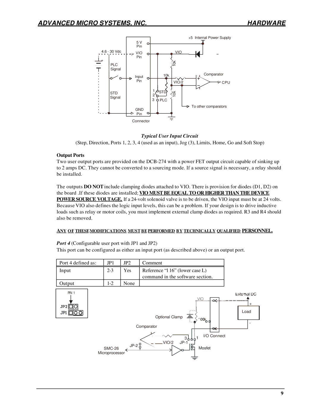
Typical User Input Circuit
(Step, Direction, Ports 1, 2, 3, 4 (used as an input), Jog (3), Limits, Home, Go and Soft Stop)
Output Ports
Two user output ports are provided on the
The outputs DO NOT include clamping diodes attached to VIO. There is provision for diodes (D1, D2) on the board .If these diodes are installed; VIO MUST BE EQUAL TO OR HIGHER THAN THE DEVICE POWER SOURCE VOLTAGE. If a
ANY O F THESEMODIFICATIONS MUST BE PERFORMED BY TECHNICALLY QUALIFIED PERSONNEL.
Port 4 (Configurable user port with JP1 and JP2)
This port can be configured as either an input port (as described above) or an output port.
| Port 4 defined as: | JP1 | JP2 | Comment |
| |||||||
|
|
|
|
|
|
|
|
|
|
|
|
|
| Input | Yes | Reference “l 16” (lower case L) |
| ||||||||
|
|
|
|
|
|
|
|
| command in the software section. |
| ||
| Output | None |
|
|
|
| ||||||
|
|
|
|
|
|
|
|
|
|
|
|
|
| PIN 1 |
|
|
|
|
|
| |||||
|
|
|
|
|
|
|
|
| VIO |
|
| |
|
|
|
|
|
|
|
|
|
| |||
|
|
|
|
|
|
|
|
| + | |||
|
|
|
|
|
|
|
|
|
|
|
|
|
|
|
| Load |
Optional Clamp |
|
| |
Comparator |
|
| - |
|
|
| |
| 3 | 1 | I/O Connect |
|
| ||
VIO/2 |
|
| |
|
| Mosfet | |
|
| ||
Microprocessor |
|
|
|
9