ADVANCED MICRO SYSTEMS, INC. | HARDWARE |
Step and Direction Inputs (J1)
A 10k
Pin | Signal |
6Ground, common with the power supply input
11Step pulse input
12Direction input
The recommended step input is a negative going pulse 5 volt TTL or CMOS.
Encoder Inputs (J1)
Optional encoder circuitry can be specified with the
Note: If the encoder produces steps too fast, the step motor can stall if it is physically unable to follow the abrupt changes in rate and/or direction.
A 10k
Pin | Signal |
6Ground, common with the power supply input
75 volts. Can be used to power an encoder with low current requirements.
11Encoder Phase A
12Encoder Phase B
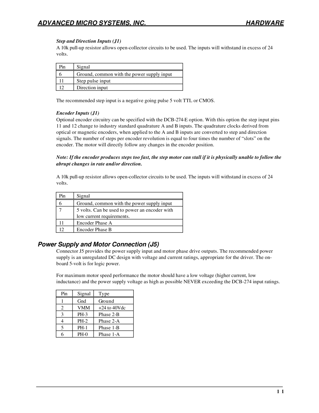
Power Supply and Motor Connection (J5)
Connector J5 provides the power supply input and motor phase drive outputs. The recommended power supply is an unregulated DC design with voltage and current ratings, appropriate for the driver. The on- board
For maximum motor speed performance the motor should have a low voltage (higher current, low inductance) and the power supply voltage as high as possible NEVER exceeding the
Pin | Signal | Type |
|
|
|
1 | Gnd | Ground |
2 | VMM | +24 to 40Vdc |
3 | Phase | |
4 | Phase | |
5 | Phase | |
6 | Phase |
1 1