Contents
Nashua, NH
Page
Revision Date 07/05/06
Page
Advanced Micro SYSTEMS, INC
Addenum
Limitations or Exceptions for the DCB-274
Introduction
Product Overview
Features
SIN-8
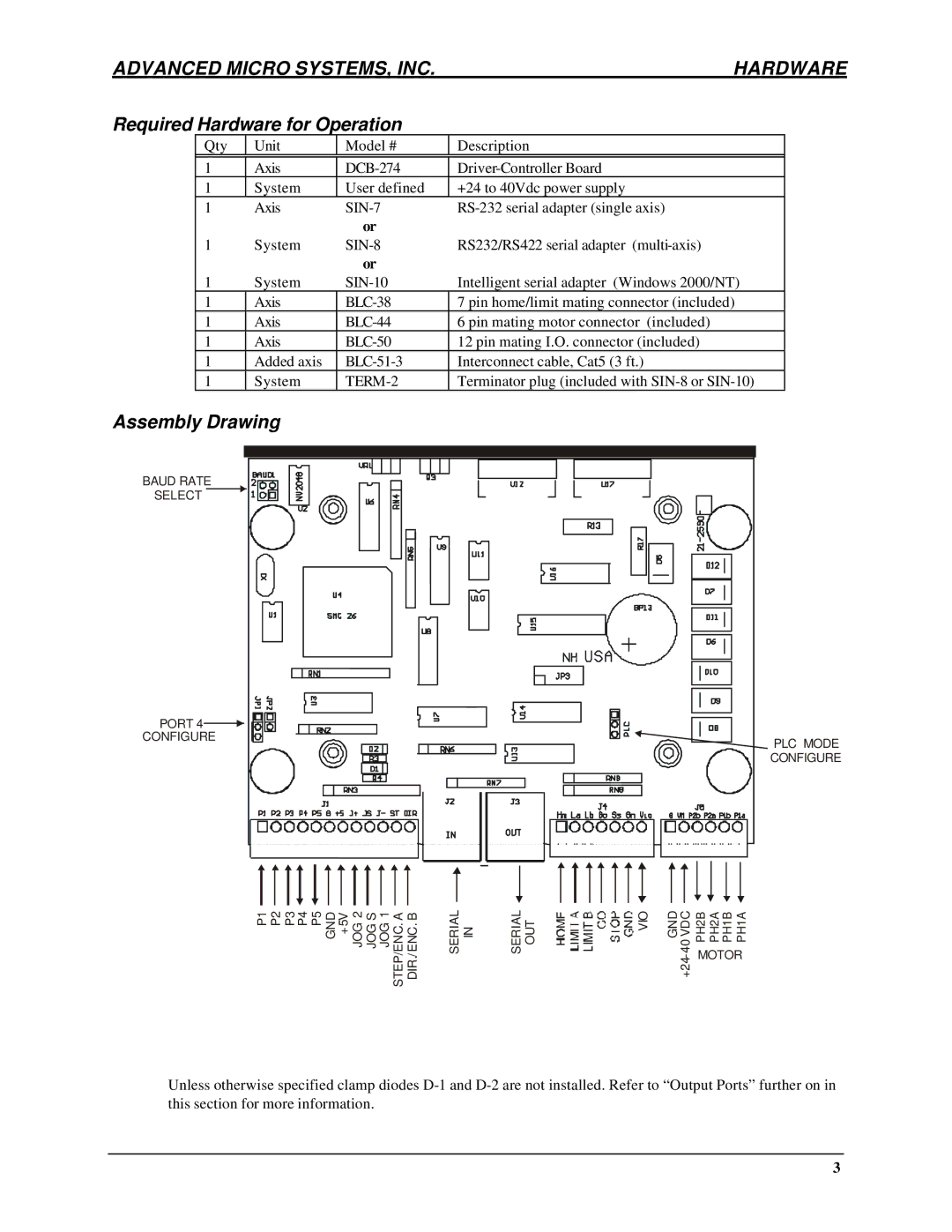
Required Hardware for Operation
Out of the Box Quick Start
After Sign-on
Connect the Motor
Dual Ammeter Circuit
Serial Interface J2, J3
Connections J1, J4
Advanced Micro SYSTEMS, INC Hardware
Input Ports
Pin 7 VIO Reference Input
Standard Mode- Sinking Inputs
PLC Mode- Sourcing Inputs
Output Ports
Typical User Input Circuit
Encoder Input Option J1
Port
Typical Output Circuit
Power Supply and Motor Connection J5
Step and Direction Inputs J1
Encoder Inputs J1
Baud Rate Jumpers B1, B2
Typical Wiring Diagrams for Step Motors
Electrical
Specifications
Environmental
Physical
Physical Dimensions
RS-232 Hardware
Overview
RS-232
RS-422
RS-232 Daisy Chain connection
Single axis, RS-232 connection using AMS SIN-7 adapter
RS-422 Party Line Hardware
Cable Specifications
Party Line Connect
RS-422 Party Line
SIN-8 Serial Adapter
RS-422/485 BUS-drop
SIN-8, RS-232 to RS-422 converter
Other Party Line Signals
SIN-10 Intelligent Serial Adapter
SIN-10, intelligent serial line converter
Daisy Chain Mode not recommended for more than 1 axis
Party Line Mode
Serial Communications Overview
Serial Communications Software
Baud Rate
Serial Interface Using Easi
Easi Software
Sign-On
Examine Command
Simple Command Examples
Daisy Chain Start-Up
Axis Name Assignment
NV Memory Programming
Verify the Program
Execute the Program
Party Line and Daisy Chain Line Commands
Edit Program
Some Rules
Party Line Startup
Command Example
Anatomy of Instruction Execution
Command Cycle Examples
Interrupt Commands
Advanced Micro SYSTEMS, INC Serial Interface
Advanced Micro SYSTEMS, INC Serial Interface
Memory Map
Non-Volatile Memory Details
Turbo Ram
Default Table
Command Format Description
ESC Global Abort
@ Soft Stop
Port Read/Write
Reset
Inputs
Outputs
Programming Example
Lower case B Fast and Slow Decay
Set Jog Speeds
Divide Speeds
Clear and Restore NV Memory
Normally Open Home Switch
Normally Closed Home Switch
Find Home
Special case Go
Initial Velocity
Step Resolution
Lower case I Restart Special Trip
Jump to Address a, n+1 times
Ramp Slope
Lower case K Trip Output Value
Advanced Micro SYSTEMS, INC SMC-27X2 Software
Loop on Port
Lower case L Option Flags
Flags and Numbers
Limit Polarity Flag
PLC Mode Flag
Make Step and Direction Outputs Flag
Moving Output Flag
Move at a Constant Velocity
Port 4 Input Flag
Gentle Limit Flag
Set Origin
Program Mode
Index Relative to Origin
Trip Point
Save
Set Slew Speed
Lower case W Pre-energize
Wait
Hold and Run Current
Examine
Read Position
Read Limits, Hardware
Read NV Memory
Index in Minus Direction
+ Index in Plus Direction
\ Write to NV Memory
Read Moving Status
Name Axis
Selective Termination
AMS SIN-11 Serial Adapter
Party Line Mode
Advanced Micro SYSTEMS, INC Addendum
Command Summary
Ctrl Char Dec Hex Code
Ascii Character Code
About Step Motor Current
Step Motor Characteristics
Determining the Current Value
Motor Choice
Basic 8 Wire Motor
Amps and Wire Count and Power
Wire Motor
Decay Control
Application Notes V1.10 Double Speed Characteristics
Serial Adapter Summary