ADVANCED MICRO SYSTEMS, INC. | HARDWARE |
As an output (as shipped) the signal can be redefined as a stepping pulse output with the “l 2” (lower case L) command. This also defines P5 as a direction output signal.
Port 5
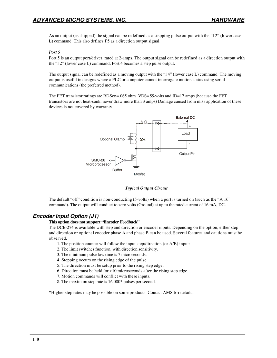
Port 5 is an output port/driver, rated at
The output signal can be redefined as a moving output with the “l 4” (lower case L) command. The moving output is useful in designs where a PLC or computer cannot interrogate motion status using serial communications (the preferred method).
The FET transistor ratings are RDSon=.065 ohm, VDS=
VIO
Optional Clamp
Microprocessor
Buffer
Mosfet
![]() +
+
Load
-
Output Pin
Typical Output Circuit
The default “off” condition is
Encoder Input Option (J1)
This option does not support “Encoder Feedback”
The
1.The position counter will follow the input step/direction (or A/B) inputs.
2.The limit switches function, with direction sensitivity.
3.The minimum pulse low time is 7 microseconds.
4.Stepping occurs on the rising edge of the pulse.
5.The direction must be setup prior to the rising step edge.
6.Direction must be held for >10 microseconds after the rising step edge.
7.Motion commands will conflict with these inputs.
8.The maximum step rate is 16,000* pulses per second.
*Higher step rates may be possible on some products. Contact AMS for details.
1 0
