Page
Page
Contents
Page
Page
Page
159
General Configuration Directives 159
Configuration Directives used during Power Failures 161
Configuration Directive Reference
164
Page
List of Figures
List of Tables
New Features
Apcupsd User’s Manual Release Notes
Change Log for current version
Change Log for older versions
Page
How To Use This Manual
Basic User’s Guide Planning Your Installation
Quick Start for Beginners
Page
Supported Operating Systems, UPSes and Cables
Page
UPS
APC Model
Upstype Upscable
Not
RS/XS
USB
APC USB, ES USB
USB UPS
Apcupsd Known USB Issues
Configuration types
More details are provided in the following section
Checking Out Your USB Subsystem
Page
Where you should get
You should get
Or perhaps something like
BUS=usb, SYSFSidVendor=051d, NAME=usb/hiddev%n
CON
USB Dynamic Minors
Cd apcupsd-source/examples make hid-ups
Known Issues with BSD USB
Platforms & Versions
Kernel Configuration
Checking UPS is Recognized by the Kernel
Apcupsd Configuration
Making Device Nodes
Red Hat Linux
Building and Installing apcupsd
Installation from Binary Packages
Microsoft Windows
Installation from Source
Verifying a Source Installation
Sbin/apcupsd $ whereis apcupsd
Configure Options
Page
Page
Recommended Options for most Systems
For most systems, we recommend the following options
You can get a listing of all available options by doing
Compilers and Options
Or for example on the Sun Solaris system, you can use
Or simply see the previous section of this manual
Operating System Specifics
Alpha
This port is complete Is operation by several users
Debian Build Install Procedures are Somewhat Particular
Debian
FreeBSD
NetBSD
OpenBSD
Red Hat Systems
Slackware
Sun Solaris
Page
Usr/ccs/bin/make install
Page
Eeprom com1-noprobe=true Eeprom com2-noprobe=true
Windows Systems with Cygwin Installed
Unknown System
Checking Your Configuration File
After Installation
To install apcupsd, do
After which, you can do a
Arranging for Reboot on Power-Up
Making sure apcupsd Is Running
Configuration Examples
Simple USB Configuration
On Suse systems
Simple Configuration for a SmartUPS
Simple Configuration for a Simple Signaling or Dumb
Simple Master Configuration
Simple Slave Configuration
Sample NIS Slave Configuration Using the Net Driver
Variation on the Master/Slave Configuration
Upsmode disable Nettime
Testing Apcupsd
After you start apcupsd, execute the following command
Process-Status Test
Apcmain Etc/apcupsd/apcupsd.conf
Apcaccess Test
Logging Test
You should see output that looks similar to the following
To run the apcaccess test, use the following command
Your apcupsd.conf file
Upsiden
Communications Test
If you see a message to the effect
Simulated Power Fail Test
Power failure. Running on UPS batteries
When it is commented out, it looks like
System Shutdown Test
Full Power Down Test
Apctest
Look at the Shutdown grace delay
Shutdown Sequence
Or on Windows systems with
Page
Some Cheaper Models Do Not Have Battery Charge
Troubleshooting Your Installation
Known Problems with USB UPSes
Reconnection does not clean up the lockfile
Monitoring and Tuning your UPS
Power Off killpower of UPS Does Not Work
Apcupsd Cannot Reconnect After a Reboot
Apcaccess
Your apcupsd.conf file Apcaccess status
As mentioned above, the full form of the command is
For a SmartUPS 1000 apcaccess will emit the following output
Apcaccess eprom
Apcupsd Notification and Events
Lotransfer
Apcupsd Network Monitoring CGI Programs
Setting up and Testing the CGI Programs
Hid-ups and USB Specific Information
Network Information Server NIS
Multimon.cgi
Visit
TH COLSPAN=10 BGCOLOR=#60B0B0
Multimon.cgi
Upsstats.cgi
Upsfstatus.cgi
Working Example Client Test Program
Then execute it
Tip from Carl Erhorn for Sun Systems
Http//hostname8888/cgi/multimon.cgi
Security Issues
Credits
Configuring Your Eeprom
Apcupsd No Longer Configures Eeprom
Using apctest to Configure Your Eeprom
Select function number Doing prepdevice
Maintaining Your UPS
What Various People Have to Say about Batteries
Kind of cool
Andre Hedrick Linux ATA Development
Page
Page
Page
Where Carl Suggests You Get Batteries
Here is a link to the APC Battery Store
Frequently-Asked Questions
Page
Page
Ls /dev
Device /dev/com2
Netserver on
Apcupsd Bugs
Advanced topics Customizing Event Handling
Apccontrol Command Line Options
Page
104
Master/Slave Configurations
Configuration Directives
Master/Slave Problems
Server/Slave Networking using NIS and the NET Driver
Master/Slave Shutdown
Batterylevel 5 Minutes
107
Error Messages from a Master Configuration
Error Messages from a Slave Configuration
Open stream socket
Master/Slave Connection Not Working
First Copy of apcupsd
Controlling Multiple UPSes on one Machine
Configuration
Second Copy of apcupsd
Important Steps after Installation of the Second Copy
Connecting an Snmp UPS
Support for Snmp UPSes
Snmp Specific Information
Building and Installing apcupsd
Known Problems
Configure line
Alternate Ways To Run The Network Information Server
Running the server as a child of apcupsd
Running apcnisd from Inetd
Running apcnisd Standalome
Apcupsd splits its logging into four separate types called
Apcupsd System Logging
Logging Types
Debug Data Status Events
Implementation Details
Developers Notes
First as root, you create the named pipe
Installation Windows Windows Version of apcupsd
Installation
Page
Page
Page
Cd c\apcupsd\bin apcupsd /service
Page
Installation Directory
Testing
Upgrading
128
Post Installation
Problem Areas
Utility Functions
Disclaimer
Killpower under Windows
Email Notification of Events
Power Down During Shutdown
Found under the key
Command Line Options Specific to the Windows Version
Building the Win32 Version from the Source
Connecting a Serial-Line UPS to a USB Port
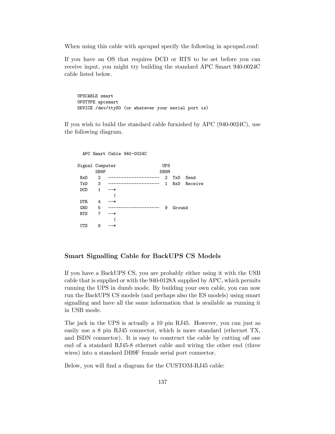
Smart-Custom Cable for SmartUPSes
Connecting a APC USB UPS to either a PC USB or Serial Port
Cables
136
Smart Signalling Cable for BackUPS CS Models
UPS DB9F
Voltage-Signalling Cable for dumb UPSes
139
140
Apcupsd SIMPLE-CUSTOM Cable
Other APC Cables that apcupsd Supports
Voltage Signalling
142
940-0020B Cable Wiring
Back-UPS Office 500 signals
It appears that the signals work as follows
Analyses of APC Cables
940-0020C Cable Wiring
Thanks to Lazar M. Fleysher
144
940-0023A Cable Wiring
940-0095A Cable Wiring
145
Shutdown
940-0095B Cable Wiring
940-0119A Cable Wiring
147
BackUPS ES and CS in Serial mode with Cable 940-0128A
BackOffice ES
Computer Inside the Connector
2N2222NPN Vvvv 2OnBatt
Win32 Implementation Restrictions for Simple UPSes
Internal Apcupsd Actions for Simple Cables
151
152
RS232 Wiring and Signal Conventions
Testing Serial-Line UPSes
Ioctl to RS232 Correspondence
Establishing Serial Port Connection
156
Page
It will present you with the following output
Using apctest on Serial-Line UPSses
On Win32 systems, use
Then it will present you with the following list of choices
Expected apctest Signals for a UPS
If you have configured your UPS as
Expected apctest Signals for a BackUPS Pro
Troubleshooting Serial Line communications
Determining Which Voltage-Signaling Cable You Have
Once you have established serial communications
Testing Apcupsd section One additional note applies
Recalibrating the UPS Runtime
Bizarre Intermittent Behavior
Status Logging On Serial-Line UPSes
162
BackUPS and NetUPS Simple Signals
Data Logging
163
Upscable type of cable you are using
Technical Reference Configuration Directive Reference
General Configuration Directives
Page
Configuration Directives used during Power Failures
166
Page
Page
Configuration Directives used to Control System Logging
Configuration Directives for Sharing a UPS
Upsmode disable share net sharenet are valid types
We recommend that the machine names used on the Master 172
Configuration Directives Used to Set the UPS Eprom
Sensitivity sets sensitivity level High, Medium, Low
Page
Apcupsd Status Logging
Status report format
Status Report Example
177
Status Report Fields
Page
Page
Shutown Sequence and its Discontents
Page
Apcaccess eeprom
Output should look something like the following
184
Shutdown Problems
Master/Slave Shutdown
Just after the line that reads
APC smart protocol
Startup
Windows Considerations
Diagram for cable hackers
Description
RS-232 differences
Smart Protocol
SMART-UPS
Below
BYE
Low battery only, N = no alarm
DEL
Clear
Is unable to transfer
VAC
Dip switch info
Status bits
Alert messages
Register
Interpretation of the Old Firmware Revision
196
Interpretation of the New Firmware Revision
Eeprom Values
198
On OFF
Programming the UPS Eeprom
Answers
Apcupsd RPM Packaging FAQ
Acknowledgements
Edit it to read
Spec file directly or pass it to rpmbuild on the command line
201
Credits
Contributors
Apcupsd Support and Knowledge Base Brian Schau Brian.Schau
Disclaimer no Warranty
Project Discussions Apcupsd Mailing List
204
Kernel Config
Typical USB section of a .config file might be
205
206
Interpretation of /proc/usb info on 2.4 kernels
207
208
USB
209
210
211
212
213
214
Interpretation of /proc/bus/usb info on 2.6 kernels
215
216
217
218
219
220
221
222
Index
Back-UPS Office 500 signals , 138 Bad APC magic from master
Configuration Directives used dur- ing Power Failures
FAQ
Eprom
Extbatts
Hostname
Hitrans
Hitransfer upper limit of ups batt. transfer
Inetd
Nombattv
Minlinev
MMM
Numxfers
Percent
Selftest
Sense 229
SSS
Cannot read magic from slave
Upsmode
Xoffbatt Xonbatt XXX
Cannot resolve slave name 232