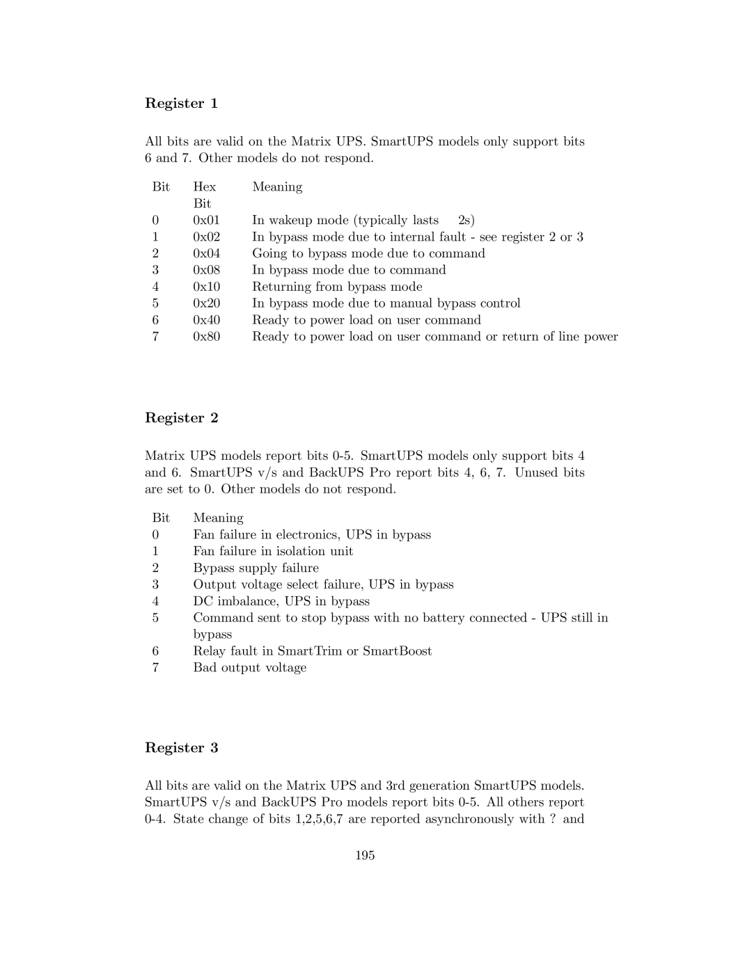
UPS control system specifications
APC UPS (Uninterruptible Power Supply) control systems are vital components for ensuring uninterrupted power supply and protecting critical equipment from power interruptions, surges, or fluctuations. Designed by Schneider Electric, APC UPS systems are renowned for their high quality and reliability. They utilize advanced technologies and features to suit diverse applications, from home offices to large industrial settings.One of the main features of APC UPS systems is the ability to provide backup power during outages. This is achieved through a battery system that activates immediately when the mains power fails. This seamless transition minimizes downtime and ensures that electronic devices continue to operate, protecting data integrity and equipment lifespan.
Another significant characteristic of APC UPS systems is their intelligent management capabilities. Most models come with PowerChute software, which provides users with real-time monitoring of power conditions and the status of the UPS. This software allows for graceful shutdowns of connected devices during extended outages, thereby preventing data loss and damage to devices.
APC UPS systems also incorporate advanced technologies such as Automatic Voltage Regulation (AVR). AVR technology ensures that the output voltage remains stable by correcting minor fluctuations without switching to battery mode. This not only prolongs the battery life but also provides a consistent power supply to the connected equipment.
Thermal management is another critical aspect of APC UPS control systems. The design often includes efficient cooling systems that prevent overheating, ensuring optimal performance and longevity of the unit. Some models feature EcoMode, which reduces energy consumption and lowers operational costs by working at high efficiency only when battery backup is not required.
APC UPS systems are designed with scalability in mind. Users can easily add more batteries or connect additional UPS units to accommodate growing power needs. Features such as hot-swappable batteries and modular design facilitate easy upgrades and servicing without interrupting power supply.
In terms of connectivity, APC UPS products often feature multiple options including USB, RS-232, and network management capabilities. This enables users to connect remote management tools and integrate the UPS with existing IT infrastructure.
In summary, APC UPS control systems deliver reliability, efficiency, and advanced technology features that cater to a wide array of power protection needs, making them a trusted choice for individuals and businesses alike.
