Important: If the power does not come on, check the next section to ensure you are using the correct cabling.
2.6 Connecting to the Network
The switch may be connected to an Ethernet network with the unit powered on or off. Use the following procedure to make your network connections:
1.Connect your network devices to the switch, following the cable guidelines outlined below.
2.After the unit is connected to the network, it can be configured for management capabilities (see the following chapters for information on configuration).
2.6.110/100BaseT Ports Cabling Procedures
The 10/100 ports on the IntraCore 3500 series allow for the connection of 10BaseT or 100BaseTX network devices. The ports are compatible with IEEE 802.3 and 802.3u standards.
Important: The switch must be located within 100 meters of its attached 10BaseT or 100BaseTX devices.
Use the following guidelines to determine the cabling requirements for your network devices:
•Connecting to Network Station: Category 5 UTP (Unshielded Twisted- Pair)
•Connecting to Repeater/Hub/Switch’s Uplink port: Category 5, UTP
Note: There aren’t specific uplink ports on these switches. All 10/100 ports on these switches are
10/100 ports will automatically determine whether the device at the other end of the link is a hub, switch or workstation, and adjust its signals accordingly.
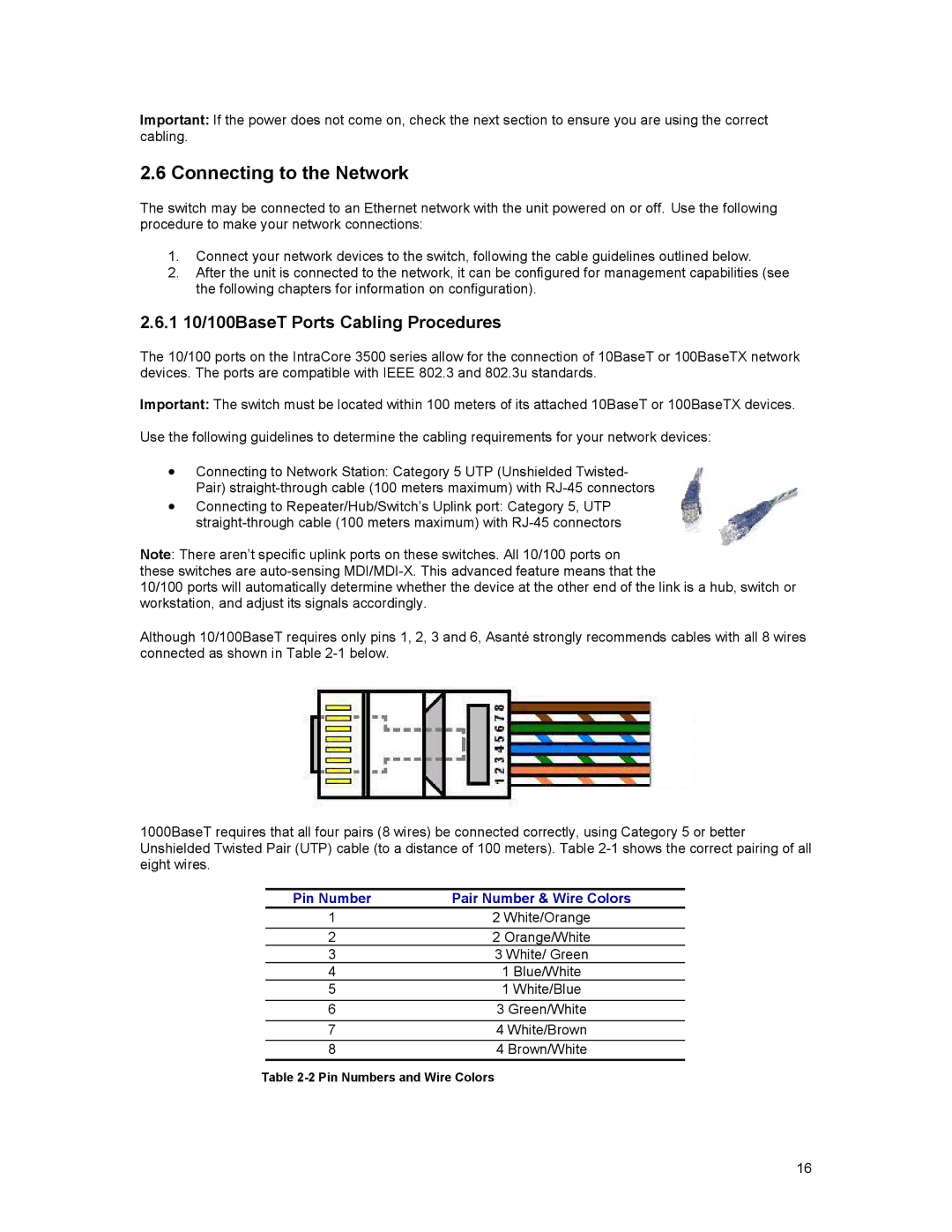
Although 10/100BaseT requires only pins 1, 2, 3 and 6, Asanté strongly recommends cables with all 8 wires connected as shown in Table
1000BaseT requires that all four pairs (8 wires) be connected correctly, using Category 5 or better Unshielded Twisted Pair (UTP) cable (to a distance of 100 meters). Table
Pin Number | Pair Number & Wire Colors |
1 | 2 White/Orange |
2 | 2 Orange/White |
3 | 3 White/ Green |
4 | 1 Blue/White |
5 | 1 White/Blue |
6 | 3 Green/White |
7 | 4 White/Brown |
8 | 4 Brown/White |
Table
16