2.2.1 Equipment Rack Guidelines
Use the following guidelines to ensure that the switch will fit safely within the equipment rack:
•Size: 17.25 x 10.0 x 1.8 inches (423 x 245 x 39 mm)
•Ventilation: Ensure that the rack is installed in a room where the temperature remains below 40° C (104° F). Be sure that there are no obstructions, such as other equipment or cables, blocking airflow to or from the vents of the switch
•Clearance: In addition to providing clearance for ventilation, ensure that there is adequate clearance for servicing the switch from the front
2.3GBIC Interfaces
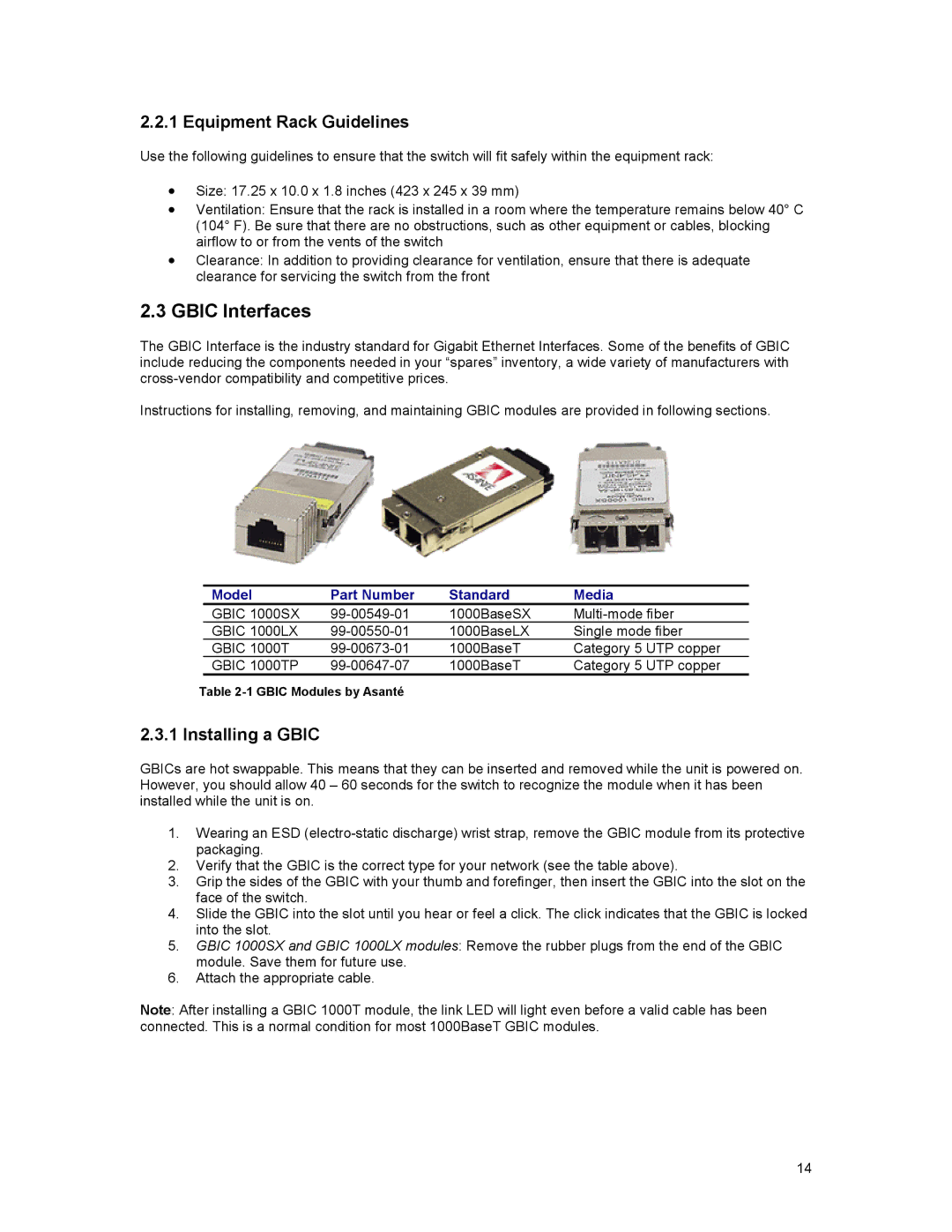
The GBIC Interface is the industry standard for Gigabit Ethernet Interfaces. Some of the benefits of GBIC include reducing the components needed in your “spares” inventory, a wide variety of manufacturers with
Instructions for installing, removing, and maintaining GBIC modules are provided in following sections.
Model | Part Number | Standard | Media |
GBIC 1000SX | 1000BaseSX | ||
GBIC 1000LX | 1000BaseLX | Single mode fiber | |
GBIC 1000T | 1000BaseT | Category 5 UTP copper | |
GBIC 1000TP | 1000BaseT | Category 5 UTP copper |
Table
2.3.1 Installing a GBIC
GBICs are hot swappable. This means that they can be inserted and removed while the unit is powered on. However, you should allow 40 – 60 seconds for the switch to recognize the module when it has been installed while the unit is on.
1.Wearing an ESD
2.Verify that the GBIC is the correct type for your network (see the table above).
3.Grip the sides of the GBIC with your thumb and forefinger, then insert the GBIC into the slot on the face of the switch.
4.Slide the GBIC into the slot until you hear or feel a click. The click indicates that the GBIC is locked into the slot.
5.GBIC 1000SX and GBIC 1000LX modules: Remove the rubber plugs from the end of the GBIC module. Save them for future use.
6.Attach the appropriate cable.
Note: After installing a GBIC 1000T module, the link LED will light even before a valid cable has been connected. This is a normal condition for most 1000BaseT GBIC modules.
14
