1.3.2 IC3548-2GT
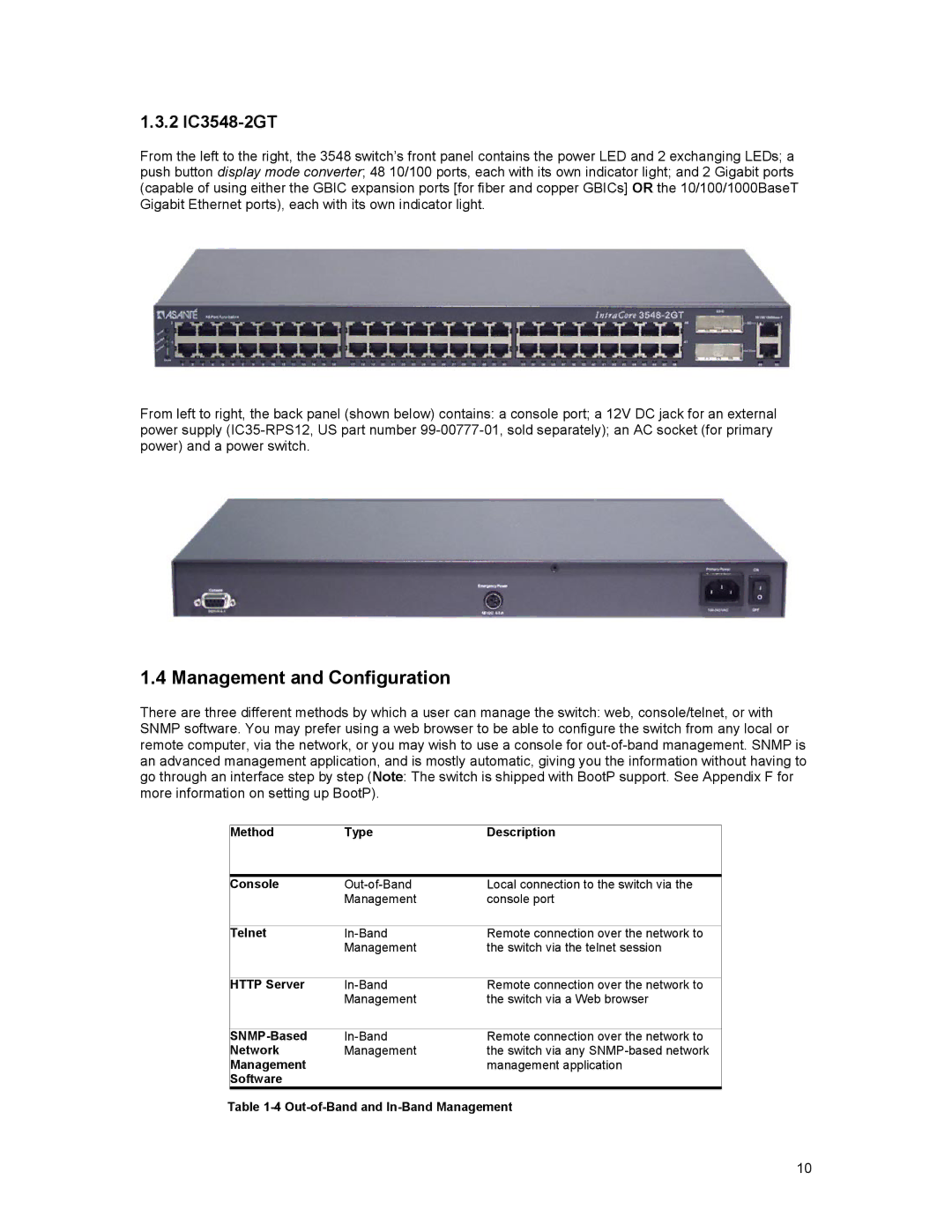
From the left to the right, the 3548 switch’s front panel contains the power LED and 2 exchanging LEDs; a push button display mode converter; 48 10/100 ports, each with its own indicator light; and 2 Gigabit ports (capable of using either the GBIC expansion ports [for fiber and copper GBICs] OR the 10/100/1000BaseT Gigabit Ethernet ports), each with its own indicator light.
From left to right, the back panel (shown below) contains: a console port; a 12V DC jack for an external power supply
1.4 Management and Configuration
There are three different methods by which a user can manage the switch: web, console/telnet, or with SNMP software. You may prefer using a web browser to be able to configure the switch from any local or remote computer, via the network, or you may wish to use a console for
Method | Type | Description |
|
|
|
Console | Local connection to the switch via the | |
| Management | console port |
|
|
|
Telnet | Remote connection over the network to | |
| Management | the switch via the telnet session |
|
|
|
HTTP Server | Remote connection over the network to | |
| Management | the switch via a Web browser |
|
|
|
Remote connection over the network to | ||
Network | Management | the switch via any |
Management |
| management application |
Software |
|
|
Table
10