Chapter 8: Installation verification
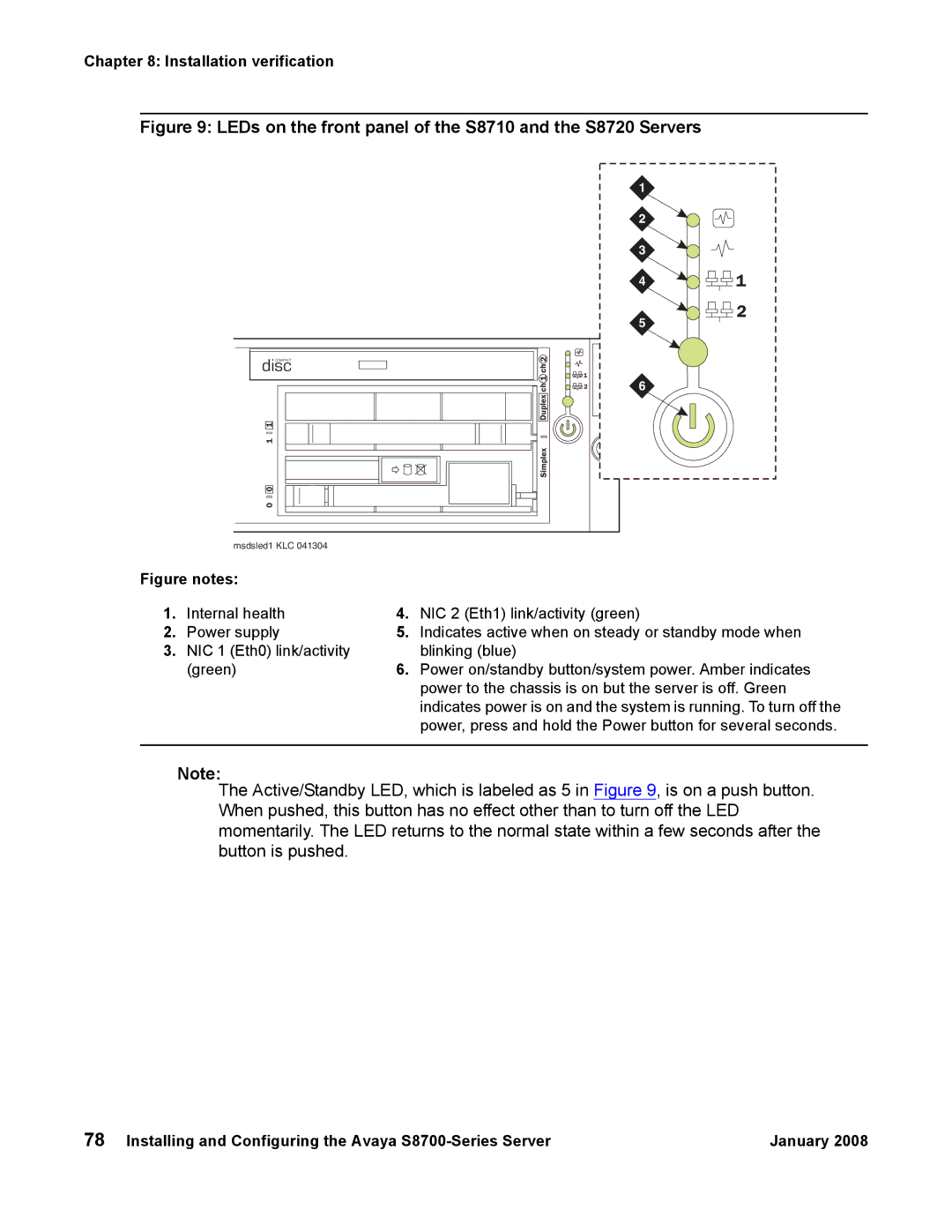
Figure 9: LEDs on the front panel of the S8710 and the S8720 Servers
|
|
| 1 |
|
|
|
| 2 |
|
|
|
| 3 |
|
|
|
| 4 | 1 |
|
|
| 5 | 2 |
|
|
|
| |
disc | ch2 |
|
|
|
COMPACT |
|
|
|
|
| ch1 | 1 | 6 |
|
| 2 |
| ||
| Duplex |
|
|
|
1 |
|
|
|
|
1 |
|
|
|
|
| Simplex |
|
|
|
0 |
|
|
|
|
0 |
|
|
|
|
msdsled1 KLC 041304 |
|
|
|
|
Figure notes:
1. | Internal health | 4. | NIC 2 (Eth1) link/activity (green) |
2. | Power supply | 5. | Indicates active when on steady or standby mode when |
3. | NIC 1 (Eth0) link/activity |
| blinking (blue) |
| (green) | 6. | Power on/standby button/system power. Amber indicates |
|
|
| power to the chassis is on but the server is off. Green |
|
|
| indicates power is on and the system is running. To turn off the |
|
|
| power, press and hold the Power button for several seconds. |
|
|
|
|
Note:
The Active/Standby LED, which is labeled as 5 in Figure 9, is on a push button. When pushed, this button has no effect other than to turn off the LED momentarily. The LED returns to the normal state within a few seconds after the button is pushed.
78 Installing and Configuring the Avaya | January 2008 |
