Chapter 8: Installation verification
S8730 LEDs
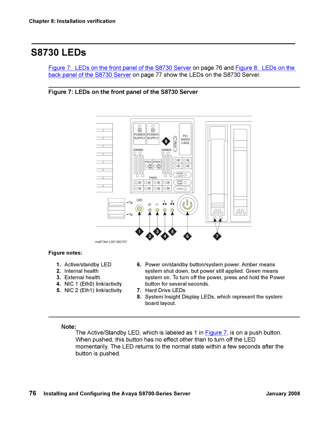
Figure 7: LEDs on the front panel of the S8730 Server on page 76 and Figure 8: LEDs on the back panel of the S8730 Server on page 77 show the LEDs on the S8730 Server.
Figure 7: LEDs on the front panel of the S8730 Server
POWER POWER
SUPPLY SUPPLY
8
DIMMSDIMMS
PROC PROC
FANS
| PCI |
PPM | RISER |
CAGE |
INTER
LOCK
OVER
TEMP
UID | 1 | 2 |
|
1 | 3 | 5 |
|
2 | 4 | 6 | 7 |
ms873lef LAO 082707
Figure notes:
1. | Active/standby LED | 6. | Power on/standby button/system power. Amber means |
2. | Internal health |
| system shut down, but power still applied. Green means |
3. | External health |
| system on. To turn off the power, press and hold the Power |
4. | NIC 1 (Eth0) link/activity |
| button for several seconds. |
5. | NIC 2 (Eth1) link/activity | 7. | Hard Drive LEDs |
|
| 8. | System Insight Display LEDs, which represent the system |
|
|
| board layout. |
Note:
The Active/Standby LED, which is labeled as 1 in Figure 7, is on a push button. When pushed, this button has no effect other than to turn off the LED momentarily. The LED returns to the normal state within a few seconds after the button is pushed.
76 Installing and Configuring the Avaya | January 2008 |
