MEASUREMENT & INSPECTION
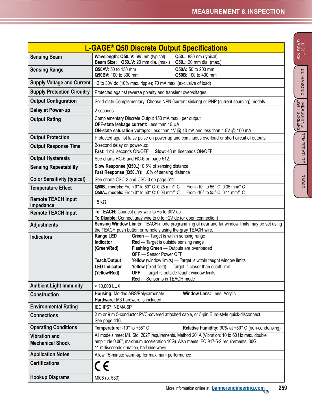
L-GAGE® Q50 Discrete Output Specifications
Sensing Beam | Wavelength: Q50..V: 685 nm (typical) | Q50..: 880 nm (typical) | ||
| Beam Size: Q50..V: 20 mm dia. (max.) | Q50..: 20 mm dia. (max.) | ||
Sensing Range | Q50AV: 50 to 150 mm | Q50A: 50 to 200 mm | ||
| Q50BV: 100 to 300 mm | Q50B: 100 to 400 mm | ||
Supply Voltage and Current | 12 to 30V dc (10% max. ripple); 70 mA max. (exclusive of load) | |||
|
| |||
Supply Protection Circuitry | Protected against reverse polarity and transient overvoltages | |||
|
| |||
Output Configuration | ||||
|
|
|
|
|
Delay at | 2 seconds |
|
|
|
|
| |||
Output Rating | Complementary Discrete Output 150 mA max., per output | |||
|
| |||
| ||||
Output Protection | Protected against false pulse on | |||
|
|
|
| |
Output Response Time |
|
| ||
| Fast: 4 milliseconds ON/OFF Slow: 48 milliseconds ON/OFF | |||
Output Hysteresis | See charts |
|
| |
|
| |||
Sensing Repeatability | Slow Response (Q50..): 0.5% of sensing distance | |||
| Fast Response (Q50..Y): 1.0% of sensing distance | |||
Color Sensitivity (typical) | See charts |
| ||
|
|
| ||
Temperature Effect | Q50B.. models: From 0° to 50° C: 0.25 mm/° C | From | ||
| Q50A.. models: From 0° to 50° C: 0.08 mm/° C | From | ||
Remote TEACH Input | 15 kΩ |
|
|
|
Impedance |
|
|
| |
|
|
|
| |
Remote TEACH Input | To Teach: Connect gray wire to +5 to 30V dc |
| ||
| To Disable: Connect gray wire to 0 to +2V dc (or open connection) | |||
Adjustments | Sensing Window Limits: | |||
| the Teach push button or remotely using the gray Teach wire. | |||
Indicators | Range LED | Green — Target is within sensing range | ||
| Indicator | Red — Target is outside sensing range | ||
| (Green/Red) | Flashing Green — Outputs are overloaded | ||
|
| OFF — Sensor Power OFF |
| |
| Teach/Output | Yellow (window limits) — Target is within taught window limits | ||
| LED Indicator | Yellow (fixed field) — Target is closer than cutoff limit | ||
| (Yellow/Red) | OFF — Target is outside taught window limits | ||
|
| Red — Sensor is in TEACH mode | ||
Ambient Light Immunity | < 10,000 LUX |
|
|
|
|
|
|
| |
Construction | Housing: Molded ABS/Polycarbonate |
| Window Lens: Lens: Acrylic | |
| Hardware: M3 hardware is included |
|
| |
Environmental Rating | IEC IP67; NEMA 6P |
|
|
|
|
| |||
Connections | 2 m or 9 m | |||
| See page 416. |
|
|
|
Operating Conditions | Temperature: |
| Relative humidity: 90% at +50° C | |
|
| |||
Vibration and | All models meet Mil. Std. 202F requirements. Method 201A (Vibration: 10 to 60 Hz max. double | |||
Mechanical Shock | amplitude 0.06”, maximum acceleration 10G). Also meets IEC | |||
| 11 milliseconds duration, half sine wave. |
|
| |
Application Notes | Allow | |||
|
|
|
|
|
Certifications |
|
|
|
|
|
|
|
|
|
Hookup Diagrams | MI08 (p. 533) |
|
|
|
|
|
|
|
|
LIGHT ULTRASONIC MEASURING TEMPERATURE RADAR
GAUGINGLIGHT SCREENS
More information online at bannerengineering.com | 259 |