|
|
|
| MEASUREMENT & INSPECTION | |||||
|
|
|
|
|
|
| |||
|
|
|
|
| |||||
Power Requirements | 16 to 30V dc @ 1.25 amps max. (see current requirements for sensors); controller alone, |
|
| ||||||
| (without sensors connected) requires 0.1 amp. |
|
|
|
|
|
|
|
|
Inputs | Sensor input (5 connections): Emitter and receiver wire in parallel to five terminals |
|
|
| |||||
| Trigger (Gate) input: Optically isolated, requires 10 to 30V dc (7.5K input impedance) for gate signal | ||||||||
Discrete Outputs |
|
|
|
| |||||
| 10 VA max. resistive load |
|
|
|
| ||||
| Output 2 (ALARM) - Open collector NPN transistor rated 30V dc max., 150 mA max, |
|
| ||||||
|
|
| |||||||
| alarm output, or a scan trigger output for a parallel array |
|
|
|
| ||||
|
|
|
|
|
| ||||
|
|
| |||||||
|
|
|
|
|
|
|
| ||
|
|
|
|
|
|
|
| ||
| transistor rated 30V dc max. 150 mA max, short circuit protected; may be configured as a | ||||||||
| second data analysis output, a system alarm output, or a scan trigger output for a parallel array | ||||||||
|
|
|
|
| |||||
|
|
| |||||||
| |||||||||
| protected; may be configured as a data analysis output, a system alarm output, or a | ||||||||
| scan trigger output for a parallel array |
|
|
|
|
|
|
| |
|
|
|
|
| |||||
| |||||||||
|
|
|
|
|
|
|
| ||
|
|
|
|
|
|
|
| ||
| 30V dc max, 150 mA max., short circuit protected |
|
|
|
|
|
| ||
|
|
|
|
|
|
|
| ||
|
|
| |||||||
Serial Data Outputs |
|
|
|
|
|
|
|
| |
| Baud Rate: 9600, 19.2K, or 38.4K, 8 data bits, 1 start bit, 1 stop bit, even parity |
|
|
|
| ||||
| Clear data may be suppressed Header string may be suppressed in binary format |
|
|
| |||||
|
|
|
|
| |||||
Analog Outputs |
|
|
|
| |||||
|
|
|
|
| |||||
| Resolution: Span/(Number of sensor channels) | Linearity: 0.1% of Full Scale |
|
|
|
| |||
| Temperature variation: 0.01% of Full Scale/° C |
|
|
|
|
|
|
|
|
Controller Programming | All models: Via | ||||||||
| operating system and using Banner supplied software |
|
|
|
|
|
|
| |
Sensor Scan Time | All models: 55 microseconds per beam plus processing time. |
|
|
|
|
|
| ||
| The processing time is dependent on the scan analysis and the number of active outputs. |
|
| ||||||
| This timing assumes a straight scan, continuous, and TBB mode |
|
|
|
| ||||
|
|
|
|
|
|
|
| ||
|
|
|
|
|
|
|
| ||
|
|
|
|
| |||||
System Response Time | Outputs are not active for 5 seconds after system power up. Maximum response time for |
|
|
| |||||
| the system is two sensor scan cycles. |
|
|
|
|
|
|
|
|
| A scan cycle includes a sensor scan plus any serial data transmission. |
|
|
|
| ||||
| Serial transmission (if activated) follows every sensor scan. |
|
|
|
|
|
|
| |
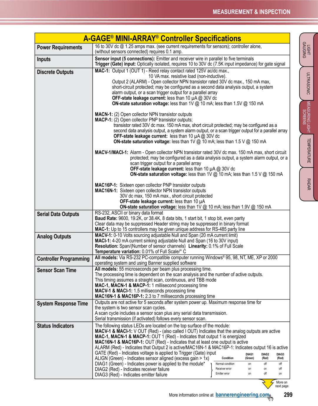
Status Indicators | The following status LEDs are located on the top surface of the module: |
|
|
|
| ||||
| |||||||||
|
|
|
| ||||||
|
|
|
| ||||||
| ALARM (Red) - Indicates that Output 2 is | ||||||||
| GATE (Red) - Indicates voltage is applied to Trigger (Gate) input | DIAG1 | DIAG2 | DIAG3 | |||||
| ALIGN (Green) - Indicates sensor aligned (excess gain > 1x) | } |
| Condition | (Green) | (Red) | (Red) |
| |
| DIAG1 (Green) - Indicates power is applied to the module* |
| Normal condition | on | off | off | |||
| DIAG2 (Red) - Indicates receiver failure |
|
| Receiver error | on | on | off | ||
| DIAG3 (Red) - Indicates emitter failure |
|
| Emitter error | on | off | on | ||
|
|
|
|
|
|
|
|
|
|
LIGHT ULTRASONIC MEASURING LIGHT TEMPERATURE RADAR GAUGINGSCREENS
More information online at bannerengineering.com | 299 |