|
|
| MEASUREMENT & INSPECTION | |
|
|
|
| |
|
|
| ||
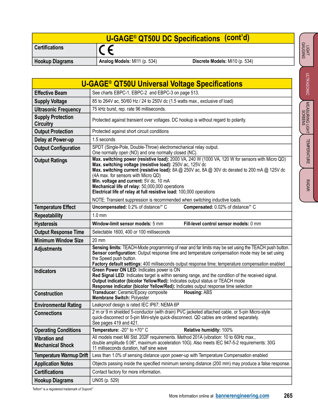
Certifications |
|
|
|
|
|
|
|
|
|
Hookup Diagrams |
| Analog Models: MI11 (p. 534) | Discrete Models: MI10 (p. 534) | |
|
|
|
| |
|
|
| ||
|
| |||
Effective Beam | See charts |
| ||
|
|
| ||
Supply Voltage | 85 to 264V ac, 50/60 Hz / 24 to 250V dc (1.5 watts max., exclusive of load) |
| ||
|
|
|
| |
Ultrasonic Frequency | 75 kHz burst, rep. rate 96 milliseconds. |
|
| |
Supply Protection | Protected against transient over voltages. DC hookup is without regard to polarity. |
| ||
Circuitry |
| |||
|
|
|
| |
Output Protection | Protected against short circuit conditions |
|
| |
|
|
|
| |
Delay at | 1.5 seconds |
|
| |
|
|
| ||
Output Configuration | SPDT |
| ||
| One normally open (NO) and one normally closed (NC). |
| ||
Output Ratings | Max. switching power (resistive load): 2000 VA, 240 W (1000 VA, 120 W for sensors with Micro QD) |
| ||
| Max. switching voltage (resistive load): 250V ac, 125V dc |
| ||
| Max. switching current (resistive load): 8A @ 250V ac, 8A @ 30V dc derated to 200 mA @ 125V dc |
| ||
| (4A max. for sensors with Micro QD) |
|
| |
| Min. voltage and current: 5V dc, 10 mA |
|
| |
| Mechanical life of relay: 50,000,000 operations |
| ||
| Electrical life of relay at full resistive load: 100,000 operations |
| ||
| NOTE: Transient suppression is recommended when switching inductive loads. |
| ||
Temperature Effect | Uncompensated: 0.2% of distance/° C | Compensated: 0.02% of distance/° C |
| |
|
|
|
| |
Repeatability | 1.0 mm |
|
| |
|
|
|
| |
Hysteresis |
| |||
|
|
|
| |
Output Response Time | Selectable 1600, 400 or 100 milliseconds |
|
| |
|
|
|
| |
Minimum Window Size | 20 mm |
|
| |
|
|
| ||
Adjustments | Sensing limits: | |||
| Sensor configuration: Output response time and temperature compensation mode may be set using |
| ||
| the Speed push button. |
|
| |
| Factory default settings: 400 milliseconds output response time; temperature compensation enabled |
| ||
Indicators | Green Power ON LED: Indicates power is ON |
|
| |
| Red Signal LED: Indicates target is within sensing range, and the condition of the received signal. |
| ||
| Output indicator (bicolor Yellow/Red): Indicates output status or TEACH mode |
| ||
| Response indicator (bicolor Yellow/Red): Indicates output response time selection |
| ||
Construction | Transducer: Ceramic/Epoxy composite | Housing: ABS |
| |
| Membrane Switch: Polyester |
|
| |
Environmental Rating | Leakproof design is rated IEC IP67; NEMA 6P |
|
| |
|
|
| ||
Connections | 2 m or 9 m shielded | |||
|
| |||
| See pages 419 and 421. |
|
| |
Operating Conditions | Temperature: | Relative humidity: 100% |
| |
|
|
| ||
Vibration and | All models meet Mil Std. 202F requirements. Method 201A (vibration: 10 to 60Hz max., | |||
Mechanical Shock | double amplitude 0.06", maximum acceleration 10G). Also meets IEC |
| ||
11 milliseconds duration, half sine wave |
|
| ||
|
|
| ||
Temperature Warmup Drift | Less than 1.0% of sensing distance upon |
| ||
|
|
| ||
Application Notes | Objects passing inside the specified minimum sensing distance (200 mm) may produce a false response. |
| ||
|
|
|
| |
Certifications | Contact factory for more information. |
|
| |
|
|
|
| |
Hookup Diagrams | UN05 (p. 529) |
|
| |
|
|
|
|
|
Teflon® is a registered trademark of Dupont™
LIGHT ULTRASONIC MEASURING LIGHT TEMPERATURE RADAR GAUGINGSCREENS
More information online at bannerengineering.com | 265 |