243
Q50
GAGELT3
Laser Distance Gauging Sensors
Advanced time-of-flight technology at less cost
Analog & discrete outputs, or dual-discrete models
LT3, 12-24V dc
GAGELT3 Sensors
245
GAGELT3 Specifications
GAGELT3 Specifications cont’d
247
GAGELT7
Highly Accurate Time-of-Flight Laser Gauging Sensors
Discrete outputs or analog and discrete models
Retroreflective models
GAGELT7 Sensors
LT7, 18-30V dc
249
LT7PLVQ
Gage LT7 Specifications
GAGELT7 Specifications cont’d
Class 1 Infrared Sensing Laser
Class 2 Visible Alignment Laser
251
Push-button setup for custom-sized sensing windows
Gagelg
Short-range Laser Sensors
Extremely compact, self-contained design
Gage LG5, 12-30V dc
Gagelg Sensors
253
Gage LG5 and LG10 Specifications
LG10, 12-30V dc
GAGELG5 and LG10 Specifications cont’d
255
Programmable features
GAGEQ50
Low-cost LED-based Distance Measurement Sensors
Reliable sensing for varied targets
Q50 Discrete Output, 12-30V dc
GAGEQ50 Sensors
257
Q50 Discrete Output, 12-30V dc cont’d
Q50 Analog Output, 15-30V dc
GAGEQ50 Discrete Output Specifications
259
GAGEQ50 Analog Output Specifications
Resolution
Supply Voltage and Current
Supply Protection Circuitry
261
S18U
GAGEQT50U
Long-range Ultrasonic Sensor
Models Range Cable Output Data Sheet
Output Models Range Cable Operation Mode Data Sheet
GAGEQT50U Sensors
GAGEQT50U, 10-30V dc
GAGEQT50U DC Specifications
GAGEQT50U Universal Voltage Specifications
GAGEQT50U DC Specifications cont’d
265
On-board diagnostics
Two housing styles
Compact Ultrasonic Sensor
Integrated push-button programming
Gage S18U Specifications
Housing Data Models Range Cable Output Configuration Sheet
Gage S18U, 10-30V dc
267
Repeatability Temperature Effect
GAGES18U Specifications cont’d
Minimum Window Size Switching Hysteresis
QS18U
Ultrasonic
WORLD-BEAMSensor
269
WORLD-BEAMQS18U, 12-30V dc
WORLD-BEAM QS18U Sensors
Model Range Cable Options Output Sheet
WORLD-BEAM QS18U Specifications
271
Compact Sensors in Universal Housing
GAGET30U
T30U, 12-24V dc
Gage T30U Sensors
273
GAGET30U Specifications
T30U, 15-24V dc
275
Gage T30U Specifications cont’d
Sensing Performance
GAGEQ45U
Flexible Ultrasonic Sensors
GAGEQ45U Sensors
Q45U Discrete Output, 12-24V dc
GAGEQ45U Analog Output, 15-24V dc
Time Sheet
GAGEQ45U Specifications
Performance Specifications
Response Curves
Output Protection Circuitry
279
GAGEQ45U Specifications cont’d
Short Range Min. target size
GAGEQ45UR
Push-button setup
Analog and discrete output
Gage Q45UR Discrete Output, 12-24V dc
281
GAGEQ45UR Remote Sensors Specifications
GAGEQ45UR High-Gain Controllers
Product P/N Version
63060 Q45UR3BA63CQ6-63060
GAGEQ45UR Remote Sensors Specifications cont’d
283
Green flashing
Red flashing
Popular patented housing
GAGET18U
Opposed Dual Range Sensors
Dual ranges and response times
Gage T18U Specifications
Gage T18U, 12-30V dc
Response Data Models Range Cable Output Time Sheet
285
GAGET18U Specifications Cont’d
Measuring Light Screens
287
Two-Piece Measuring Light Screens
Versatile mounting
GAGEEZ-ARRAYLight Screen
EZ-ARRAY Light Screens, 12-30V dc-5 mm Beam Spacing
GAGEEZ-ARRAYSpecification
MINI-ARRAY
291
Ultra-precise monitoring & inspection
Many options, yet easy to program
Gage High-Resolution MINI-ARRAY Controllers 16-30V dc
High-Resolution MINI-ARRAYSystem
Emitter/Receiver Housing Models Length L
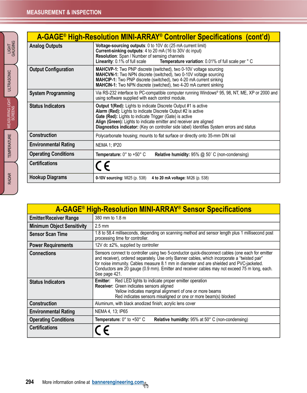
GAGEHigh-Resolution MINI-ARRAYController Specifications
293
GAGEHigh-Resolution MINI-ARRAYSensor Specifications
295
Gage MINI-ARRAY
Inspection and Profiling Light Screens
GAGEMINI-ARRAYControllers†, 16-30V dc
MAC16N-1
MAC16P-1
297
Housing Total Array
Sensors-19.1 mm Beam Spacing
Sensors-9.5 mm Beam Spacing
Data Models Cable Length Beams Object Size Range Sheet
GAGEMINI-ARRAYController Specifications
299
System Response Time
Controller Programming
Gage MINI-ARRAY Controller Specifications cont’d
Gage MINI-ARRAY Controller with DeviceNet Specifications
GAGEMINI-ARRAYSensor Specifications
Interlaced Mode 12.7 mm Interlaced Mode 25.4 mm
301
Minimum Object Sensitivity
Control Mode Selection
Alarm/Trigger
Analysis Measurement
Blanking
M18T 14 M18T 8 M18T 6
M18T Temperature Sensors
303
GAGEM18T Sensors
M18T-Discrete, 10-30V dc
M18T-Analog, 12-30V dc
Sensor Sensing Overall Output † Data Models
GAGEM18T Specifications
305
Radar-Based Adjustable-Field Sensor
GAGEQT50R
Gage QT50R, 12-30V dc
Model Max Range † Cable Telecom Approval Output Data Sheet
307
Gage QT50R Specifications