LIGHT GAUGING | ||
LABEL& |
| |
ULTRASONIC |
| |
SLOT |
| |
LIGHT |
| lUMINESCENCE |
MEASURING |
| |
| SCREENS | |
& |
| |
COLOR |
| |
TEMPERATURE |
| |
| ||
PICK |
| |
RADAR |
| |
MEASUREMENT & INSPECTION
|
|
| |
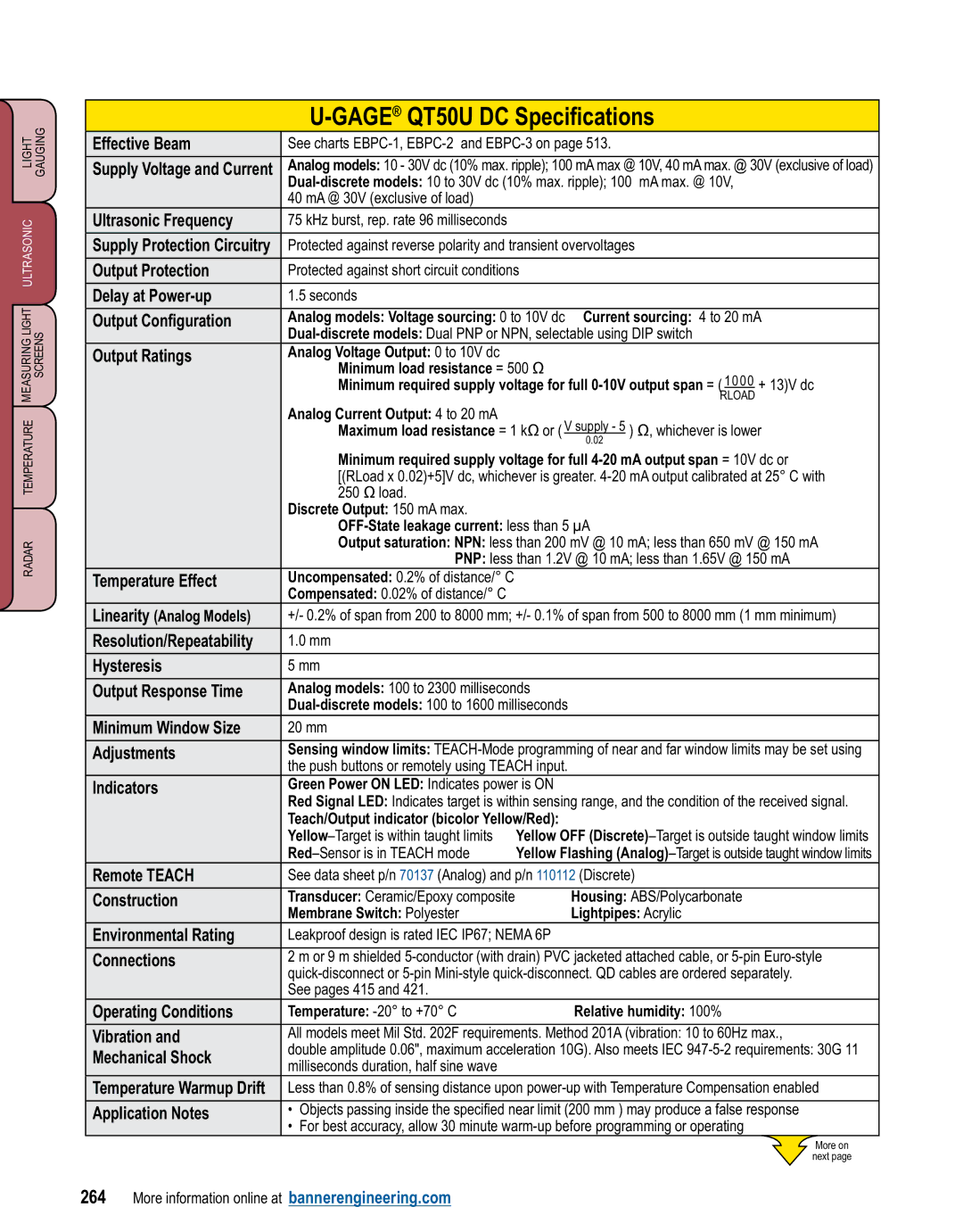
Effective Beam | See charts | ||
|
| ||
Supply Voltage and Current | Analog models: 10 - 30V dc (10% max. ripple); 100 mA max @ 10V, 40 mA max. @ 30V (exclusive of load) | ||
| |||
| 40 mA @ 30V (exclusive of load) |
| |
Ultrasonic Frequency | 75 kHz burst, rep. rate 96 milliseconds |
| |
|
| ||
Supply Protection Circuitry | Protected against reverse polarity and transient overvoltages | ||
|
| ||
Output Protection | Protected against short circuit conditions | ||
|
|
| |
Delay at | 1.5 seconds |
| |
|
| ||
Output Configuration | Analog models: Voltage sourcing: 0 to 10V dc Current sourcing: 4 to 20 mA | ||
| |||
Output Ratings | Analog Voltage Output: 0 to 10V dc |
| |
|
| Minimum load resistance = 500 Ω | |
|
| Minimum required supply voltage for full | |
|
|
| RLOAD |
| Analog Current Output: 4 to 20 mA |
| |
|
| Maximum load resistance = 1 kΩ or ( V supply - 5 ) Ω, whichever is lower | |
|
|
| 0.02 |
|
| Minimum required supply voltage for full | |
|
| [(RLoad x 0.02)+5]V dc, whichever is greater. | |
|
| 250 Ω load. |
|
| Discrete Output: 150 mA max. |
| |
|
|
| |
|
| Output saturation: NPN: less than 200 mV @ 10 mA; less than 650 mV @ 150 mA | |
|
| PNP: less than 1.2V @ 10 mA; less than 1.65V @ 150 mA | |
Temperature Effect | Uncompensated: 0.2% of distance/° C |
| |
| Compensated: 0.02% of distance/° C |
| |
Linearity (Analog Models) | +/- 0.2% of span from 200 to 8000 mm; +/- 0.1% of span from 500 to 8000 mm (1 mm minimum) | ||
|
|
| |
Resolution/Repeatability | 1.0 mm |
| |
|
|
| |
Hysteresis | 5 mm |
| |
|
| ||
Output Response Time | Analog models: 100 to 2300 milliseconds | ||
| |||
Minimum Window Size | 20 mm |
| |
|
| ||
Adjustments | Sensing window limits: | ||
| the push buttons or remotely using TEACH input. | ||
Indicators | Green Power ON LED: Indicates power is ON | ||
| Red Signal LED: Indicates target is within sensing range, and the condition of the received signal. | ||
| Teach/Output indicator (bicolor Yellow/Red): | ||
| Yellow OFF | ||
| Yellow Flashing | ||
Remote TEACH | See data sheet p/n 70137 (Analog) and p/n 110112 (Discrete) | ||
|
|
| |
Construction | Transducer: Ceramic/Epoxy composite | Housing: ABS/Polycarbonate | |
| Membrane Switch: Polyester | Lightpipes: Acrylic | |
Environmental Rating | Leakproof design is rated IEC IP67; NEMA 6P | ||
|
| ||
Connections | 2 m or 9 m shielded | ||
| |||
| See pages 415 and 421. |
| |
Operating Conditions | Temperature: | Relative humidity: 100% | |
|
| ||
Vibration and | All models meet Mil Std. 202F requirements. Method 201A (vibration: 10 to 60Hz max., | ||
Mechanical Shock | double amplitude 0.06", maximum acceleration 10G). Also meets IEC | ||
milliseconds duration, half sine wave |
| ||
|
| ||
Temperature Warmup Drift | Less than 0.8% of sensing distance upon | ||
|
|
| |
Application Notes | • | Objects passing inside the specified near limit (200 mm ) may produce a false response | |
| • | For best accuracy, allow 30 minute | |
More on
next page
264 More information online at bannerengineering.com