PICK-TO-LIGHT SCREENSGAUGING
RADAR TEMPERATURE MEASURING LIGHT ULTRASONIC LIGHT
MEASUREMENT & INSPECTION
|
| |||||
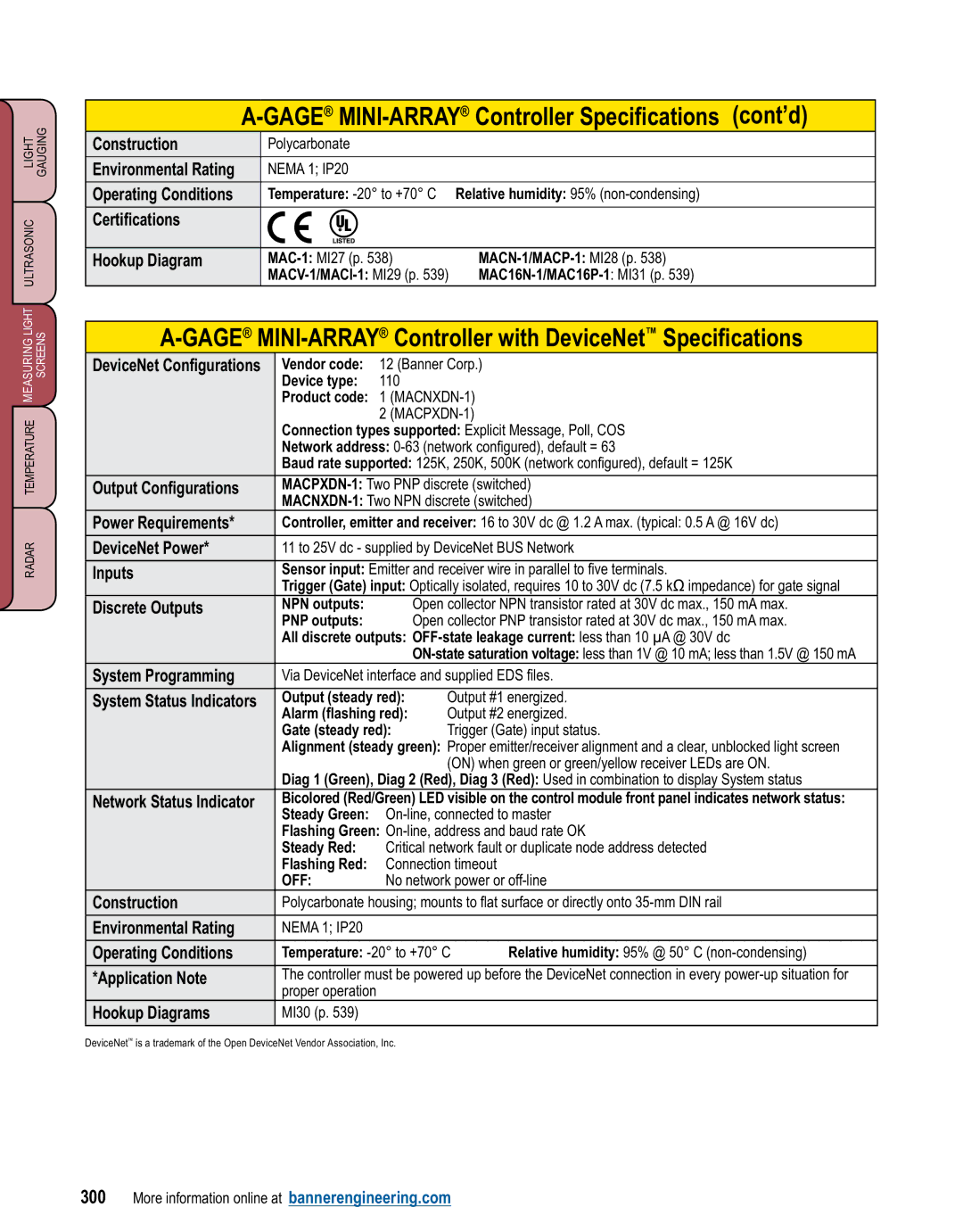
Construction | Polycarbonate |
|
|
|
| |
|
|
|
|
|
|
|
Environmental Rating | NEMA 1; IP20 |
|
|
|
| |
|
|
|
| |||
Operating Conditions | Temperature: |
| ||||
|
|
|
|
|
|
|
Certifications |
| R |
|
|
|
|
|
|
|
|
|
| |
|
|
|
|
|
| |
Hookup Diagram |
|
| ||||
|
| |||||
|
|
| ||||
|
| |||||
DeviceNet Configurations |
| Vendor code: | 12 (Banner Corp.) |
| ||
|
| Device type: | 110 |
|
|
|
|
| Product code: 1 |
|
| ||
|
|
| 2 |
|
| |
|
| Connection types supported: Explicit Message, Poll, COS |
| |||
|
| Network address: |
| |||
|
| Baud rate supported: 125K, 250K, 500K (network configured), default = 125K |
| |||
|
|
|
| |||
Output Configurations |
|
| ||||
|
|
| ||||
Power Requirements* |
| Controller, emitter and receiver: 16 to 30V dc @ 1.2 A max. (typical: 0.5 A @ 16V dc) |
| |||
|
|
|
| |||
DeviceNet Power* |
| 11 to 25V dc - supplied by DeviceNet BUS Network |
| |||
|
|
|
| |||
Inputs |
| Sensor input: Emitter and receiver wire in parallel to five terminals. |
| |||
|
| Trigger (Gate) input: Optically isolated, requires 10 to 30V dc (7.5 kΩ impedance) for gate signal |
| |||
Discrete Outputs |
| NPN outputs: |
| Open collector NPN transistor rated at 30V dc max., 150 mA max. |
| |
|
| PNP outputs: |
| Open collector PNP transistor rated at 30V dc max., 150 mA max. |
| |
|
| All discrete outputs: |
| |||
|
|
|
|
| ||
System Programming |
| Via DeviceNet interface and supplied EDS files. |
| |||
|
|
|
|
| ||
System Status Indicators |
| Output (steady red): | Output #1 energized. |
| ||
|
| Alarm (flashing red): | Output #2 energized. |
| ||
|
| Gate (steady red): | Trigger (Gate) input status. |
| ||
|
| Alignment (steady green): Proper emitter/receiver alignment and a clear, unblocked light screen |
| |||
|
|
|
| (ON) when green or green/yellow receiver LEDs are ON. |
| |
|
| Diag 1 (Green), Diag 2 (Red), Diag 3 (Red): Used in combination to display System status |
| |||
Network Status Indicator |
| Bicolored (Red/Green) LED visible on the control module front panel indicates network status: |
| |||
|
| Steady Green: |
| |||
|
| Flashing Green: |
| |||
|
| Steady Red: | Critical network fault or duplicate node address detected |
| ||
|
| Flashing Red: | Connection timeout |
| ||
|
| OFF: | No network power or |
| ||
Construction |
| Polycarbonate housing; mounts to flat surface or directly onto |
| |||
|
|
|
|
|
|
|
Environmental Rating |
| NEMA 1; IP20 |
|
|
|
|
|
|
|
|
| ||
Operating Conditions |
| Temperature: | Relative humidity: 95% @ 50° C |
| ||
|
|
|
| |||
*Application Note |
| The controller must be powered up before the DeviceNet connection in every |
| |||
|
| proper operation |
|
|
|
|
Hookup Diagrams |
| MI30 (p. 539) |
|
|
|
|
|
|
|
|
|
|
|
DeviceNet™ is a trademark of the Open DeviceNet Vendor Association, Inc.
300 More information online at bannerengineering.com