LIGHT GAUGING | ||
LABEL& |
| |
ULTRASONIC |
| |
SLOT |
| |
LIGHT |
| lUMINESCENCE |
MEASURING |
| |
| SCREENS | |
& |
| |
COLOR |
| |
TEMPERATURE |
| |
| ||
PICK |
| |
RADAR |
| |
MEASUREMENT & INSPECTION
|
|
| |
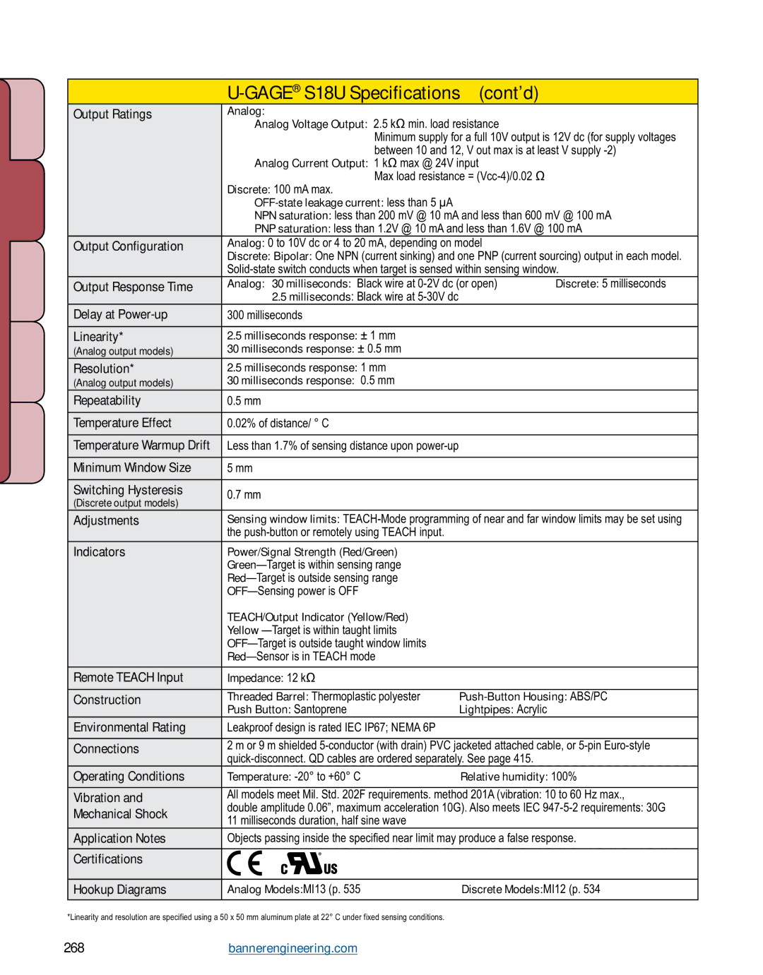
Output Ratings | Analog: |
|
|
| Analog Voltage Output: 2.5 kΩ min. load resistance |
| |
| Minimum supply for a full 10V output is 12V dc (for supply voltages | ||
| between 10 and 12, V out max is at least V supply | ||
| Analog Current Output: 1 kΩ max @ 24V input |
| |
| Max load resistance = |
| |
| Discrete: 100 mA max. |
|
|
|
|
|
|
| NPN saturation: less than 200 mV @ 10 mA and less than 600 mV @ 100 mA | ||
| PNP saturation: less than 1.2V @ 10 mA and less than 1.6V @ 100 mA | ||
Output Configuration | Analog: 0 to 10V dc or 4 to 20 mA, depending on model |
| |
| Discrete: Bipolar: One NPN (current sinking) and one PNP (current sourcing) output in each model. | ||
| |||
Output Response Time | Analog: 30 milliseconds: Black wire at | Discrete: 5 milliseconds | |
| 2.5 milliseconds: Black wire at |
|
|
Delay at | 300 milliseconds |
|
|
|
|
|
|
Linearity* | 2.5 milliseconds response: ± 1 mm |
|
|
(Analog output models) | 30 milliseconds response: ± 0.5 mm |
|
|
Resolution* | 2.5 milliseconds response: 1 mm |
|
|
(Analog output models) | 30 milliseconds response: 0.5 mm |
|
|
Repeatability | 0.5 mm |
|
|
|
|
|
|
Temperature Effect | 0.02% of distance/ ° C |
|
|
|
|
|
|
Temperature Warmup Drift | Less than 1.7% of sensing distance upon |
|
|
|
|
|
|
Minimum Window Size | 5 mm |
|
|
|
|
|
|
Switching Hysteresis | 0.7 mm |
|
|
(Discrete output models) |
|
| |
|
|
| |
Adjustments | Sensing window limits: | ||
| the |
|
|
Indicators | Power/Signal Strength (Red/Green) |
|
|
|
|
| |
|
|
| |
|
|
| |
| Teach/Output Indicator (Yellow/Red) |
|
|
| Yellow |
|
|
|
|
| |
|
|
| |
|
|
|
|
Remote TEACH Input | Impedance: 12 kΩ |
|
|
|
|
| |
Construction | Threaded Barrel: Thermoplastic polyester | ||
| Push Button: Santoprene | Lightpipes: Acrylic |
|
Environmental Rating | Leakproof design is rated IEC IP67; NEMA 6P |
|
|
|
| ||
Connections | 2 m or 9 m shielded | ||
|
| ||
Operating Conditions | Temperature: | Relative humidity: 100% | |
|
| ||
Vibration and | All models meet Mil. Std. 202F requirements. method 201A (vibration: 10 to 60 Hz max., | ||
Mechanical Shock | double amplitude 0.06”, maximum acceleration 10G). Also meets IEC | ||
11 milliseconds duration, half sine wave |
|
| |
|
|
| |
Application Notes | Objects passing inside the specified near limit may produce a false response. | ||
|
|
|
|
Certifications |
|
|
|
|
|
| |
Hookup Diagrams | Analog Models: MI13 (p. 535) | Discrete Models: MI12 (p. 534) | |
|
|
|
|
*Linearity and resolution are specified using a 50 x 50 mm aluminum plate at 22° C under fixed sensing conditions.
268 More information online at bannerengineering.com