ULTRASONIC LIGHT GAUGING
MEASUREMENT & INSPECTION
System Configuration
Many options, yet easy to program
The software included with the control module makes it easy to configure the
*Running Windows® 95, 98, NT, ME, XP or 2000
TEMPERATURE MEASURING LIGHT
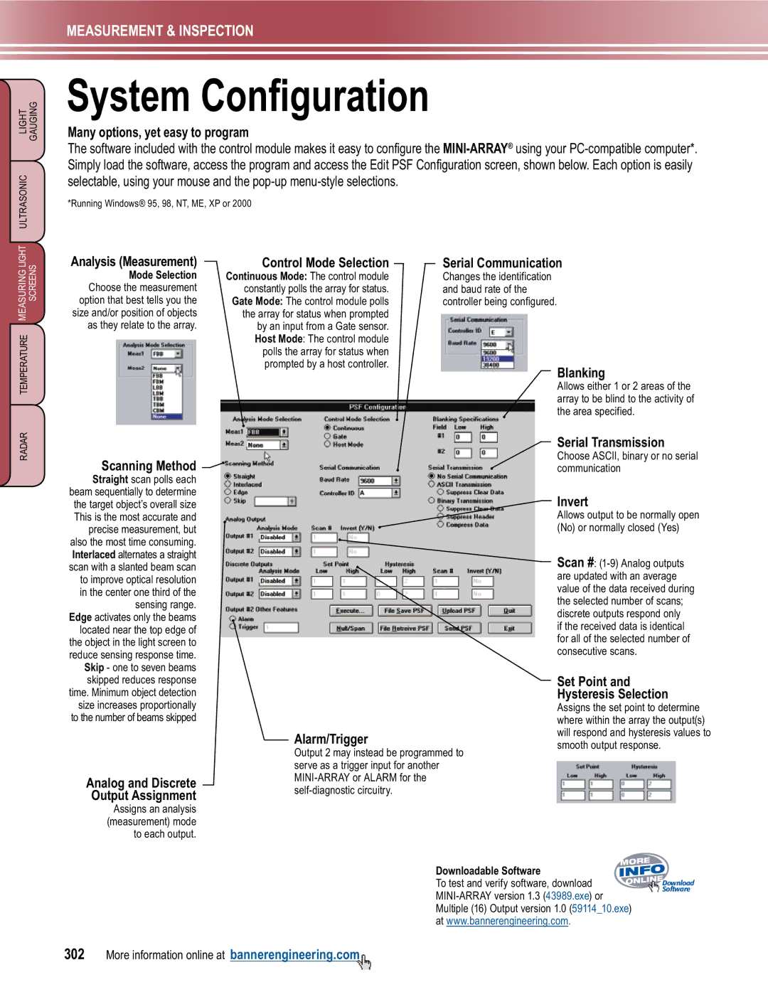
Analysis (Measurement)
Mode Selection Choose the measurement option that best tells you the size and/or position of objects as they relate to the array.
Control Mode Selection
Continuous Mode: The control module constantly polls the array for status.
Gate Mode: The control module polls the array for status when prompted by an input from a Gate sensor. Host Mode: The control module polls the array for status when prompted by a host controller.
Serial Communication
Changes the identification and baud rate of the controller being configured.
Blanking
Allows either 1 or 2 areas of the array to be blind to the activity of the area specified.
RADAR
Scanning Method 

Straight scan polls each beam sequentially to determine the target object’s overall size This is the most accurate and precise measurement, but also the most time consuming. Interlaced alternates a straight scan with a slanted beam scan to improve optical resolution in the center one third of the sensing range.
Edge activates only the beams located near the top edge of the object in the light screen to reduce sensing response time. Skip - one to seven beams skipped reduces response time. Minimum object detection size increases proportionally to the number of beams skipped
Analog and Discrete
Output Assignment
Assigns an analysis (measurement) mode to each output.
Alarm/Trigger
Output 2 may instead be programmed to serve as a trigger input for another
Serial Transmission
Choose ASCII, binary or no serial communication
Invert
Allows output to be normally open (No) or normally closed (Yes)
Scan #:
if the received data is identical for all of the selected number of consecutive scans.
Set Point and
Hysteresis Selection
Assigns the set point to determine where within the array the output(s) will respond and hysteresis values to smooth output response.
Downloadable Software |
|
To test and verify software, download | Download |
Software | |
| |
Multiple (16) Output version 1.0 (59114_10.exe) |
|
at www.bannerengineering.com. |
|
302 More information online at bannerengineering.com