MEASUREMENT & INSPECTION
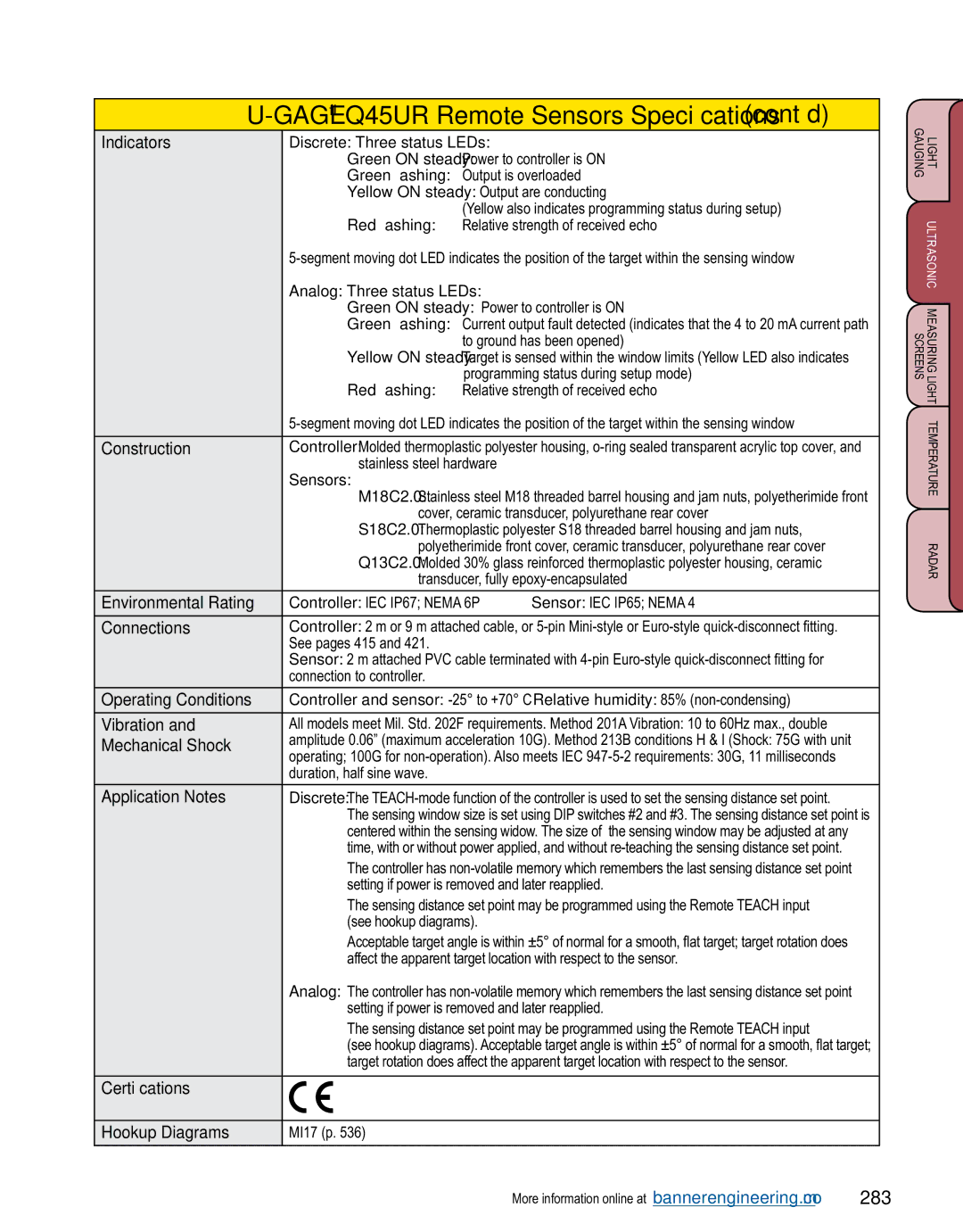
U-GAGE® Q45UR Remote Sensors Specifications (cont’d)
Indicators | Discrete: Three status LEDs: |
| ||
| Green ON steady: Power to controller is ON | |||
| Green flashing: | Output is overloaded | ||
| Yellow ON steady: Output are conducting | |||
| Red flashing: | (Yellow also indicates programming status during setup) | ||
| Relative strength of received echo | |||
| ||||
| Analog: Three status LEDs: |
|
| |
| Green ON steady: Power to controller is ON | |||
| Green flashing: | Current output fault detected (indicates that the 4 to 20 mA current path | ||
|
| to ground has been opened) | ||
| Yellow ON steady: Target is sensed within the window limits (Yellow LED also indicates | |||
| Red flashing: | programming status during setup mode) | ||
| Relative strength of received echo | |||
| ||||
|
| |||
Construction | Controller: Molded thermoplastic polyester housing, | |||
| stainless steel hardware |
| ||
| Sensors: |
|
| |
| M18C2.0: Stainless steel M18 threaded barrel housing and jam nuts, polyetherimide front | |||
| cover, ceramic transducer, polyurethane rear cover | |||
| S18C2.0: Thermoplastic polyester S18 threaded barrel housing and jam nuts, | |||
| polyetherimide front cover, ceramic transducer, polyurethane rear cover | |||
| Q13C2.0: Molded 30% glass reinforced thermoplastic polyester housing, ceramic | |||
| transducer, fully | |||
|
|
| ||
Environmental Rating | Controller: IEC IP67; NEMA 6P | Sensor: IEC IP65; NEMA 4 | ||
|
| |||
Connections | Controller: 2 m or 9 m attached cable, or | |||
| See pages 415 and 421. |
|
| |
| Sensor: 2 m attached PVC cable terminated with | |||
| connection to controller. |
|
| |
|
| |||
Operating Conditions | Controller and sensor: | |||
|
| |||
Vibration and | All models meet Mil. Std. 202F requirements. Method 201A Vibration: 10 to 60Hz max., double | |||
Mechanical Shock | amplitude 0.06” (maximum acceleration 10G). Method 213B conditions H & I (Shock: 75G with unit | |||
operating; 100G for | ||||
| ||||
| duration, half sine wave. |
|
| |
|
| |||
Application Notes | Discrete: The | |||
| The sensing window size is set using DIP switches #2 and #3. The sensing distance set point is | |||
| centered within the sensing widow. The size of the sensing window may be adjusted at any | |||
| time, with or without power applied, and without | |||
| The controller has | |||
| setting if power is removed and later reapplied. | |||
| The sensing distance set point may be programmed using the Remote TEACH input | |||
| (see hookup diagrams). |
| ||
| Acceptable target angle is within ±5° of normal for a smooth, flat target; target rotation does | |||
| affect the apparent target location with respect to the sensor. | |||
| Analog: The controller has | |||
| setting if power is removed and later reapplied. | |||
| The sensing distance set point may be programmed using the Remote TEACH input | |||
| (see hookup diagrams). Acceptable target angle is within ±5° of normal for a smooth, flat target; | |||
| target rotation does affect the apparent target location with respect to the sensor. | |||
|
|
|
| |
Certifications |
|
|
| |
|
|
|
| |
Hookup Diagrams | MI17 (p. 536) |
|
| |
|
|
|
| |
LIGHT ULTRASONIC MEASURING LIGHT TEMPERATURE RADAR GAUGINGSCREENS
More information online at bannerengineering.com | 283 |