Location and Function of Controls
2 |
|
|
| LOCATION AND FUNCTION OF CONTROLS | ||||||
|
|
| ||||||||
|
|
|
|
|
| |||||
|
|
|
|
|
|
|
|
|
|
|
|
|
|
|
|
|
|
|
|
|
|
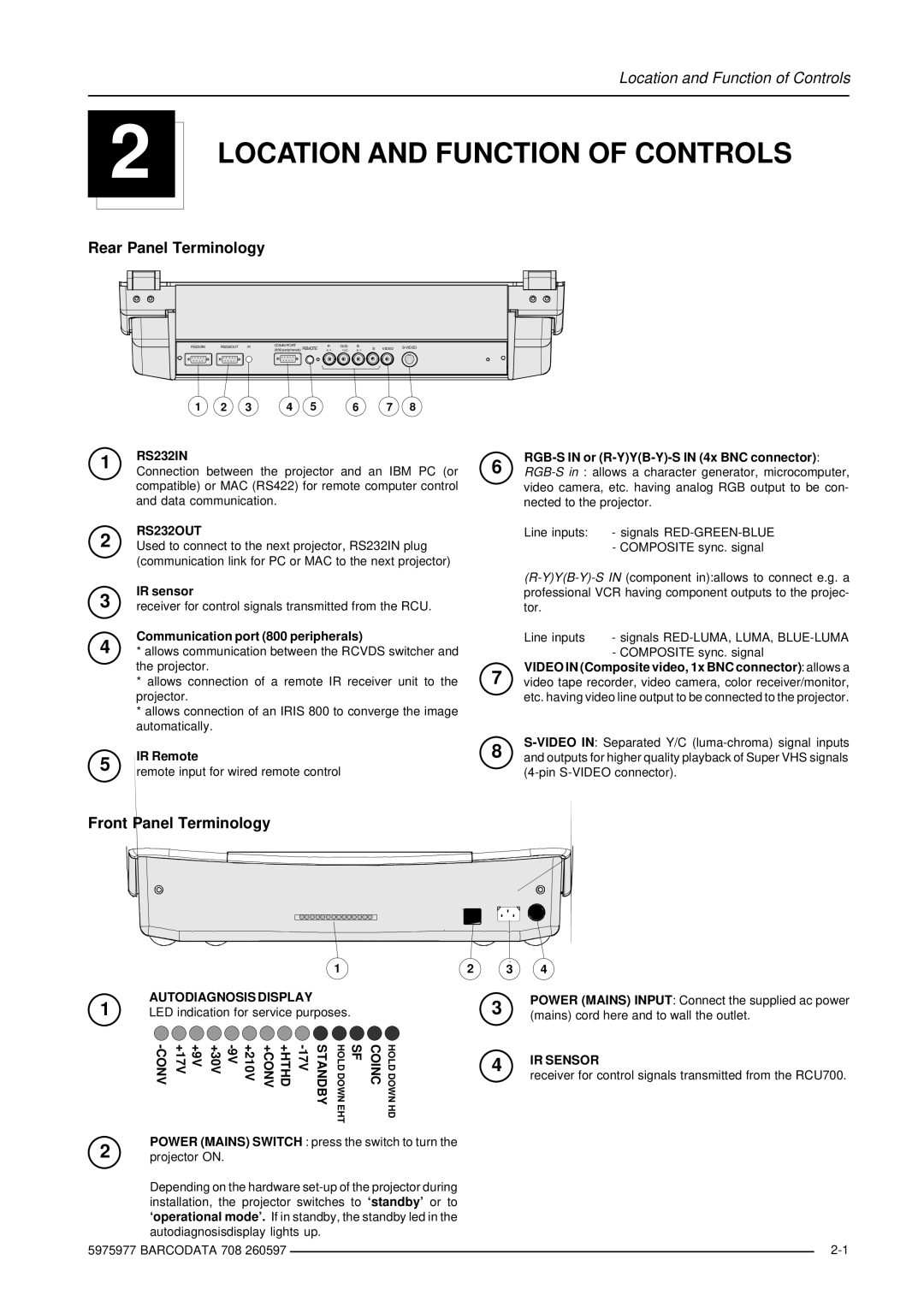
Rear Panel Terminology | ||||||||||
|
|
|
|
|
|
|
|
|
|
|
|
|
|
|
|
|
|
|
|
|
|
|
|
|
|
|
|
|
|
|
|
|
|
|
|
|
|
|
|
|
|
|
|
| RS232IN | RS232OUT | IR | COMM PORT | R | G(S) | B |
|
| |||
| (800 peripherals) REMOTE | S | VIDEO | |||||||||
|
|
|
|
| R- Y | Y(S ) | B |
| ||||
|
|
|
|
|
|
|
|
|
|
|
|
|
|
|
|
|
|
|
|
|
|
|
|
|
|
1 | 2 | 3 | 4 | 5 | 6 | 7 | 8 |
1
2
RS232IN | 6 |
|
Connection between the projector and an IBM PC (or | ||
compatible) or MAC (RS422) for remote computer control |
| video camera, etc. having analog RGB output to be con- |
and data communication. |
| nected to the projector. |
RS232OUT |
| Line inputs: - signals |
Used to connect to the next projector, RS232IN plug |
| - COMPOSITE sync. signal |
(communication link for PC or MAC to the next projector) |
|
|
3 | IR sensor |
receiver for control signals transmitted from the RCU. | |
4 | Communication port (800 peripherals) |
* allows communication between the RCVDS switcher and | |
| the projector. |
| * allows connection of a remote IR receiver unit to the |
| projector. |
| * allows connection of an IRIS 800 to converge the image |
| automatically. |
5 | IR Remote |
remote input for wired remote control |
Front Panel Terminology
Line inputs | - signals |
| - COMPOSITE sync. signal |
VIDEO IN (Composite video, 1x BNC connector): allows a
7 video tape recorder, video camera, color receiver/monitor, etc. having video line output to be connected to the projector.
8 and outputs for higher quality playback of Super VHS signals
1
AUTODIAGNOSIS DISPLAY
1 LED indication for service purposes.
+9V +17V | +210V | STANDBY | HOLD DOWN EHT | SF | COINC | HOLD DOWN HD |
2 3 4
3 | POWER (MAINS) INPUT: Connect the supplied ac power | |
(mains) cord here and to wall the outlet. | ||
| ||
4 | IR SENSOR | |
receiver for control signals transmitted from the RCU700. | ||
|
2 | POWER (MAINS) SWITCH : press the switch to turn the |
| |
projector ON. |
| ||
| Depending on the hardware |
| |
| installation, the projector switches to ‘standby’ or to |
| |
| ‘operational mode’. If in standby, the standby led in the |
| |
| autodiagnosisdisplay lights up. |
| |
5975977 BARCODATA 708 260597 |
| ||
| |||