Satellite Site “Trunk Line” Monitor Outputs
9Satellite Configuration Installations
Due to the many variations possible, only general guidelines can be covered for installing satellite systems. Refer to the Appendix Section of this manual, the
LTC 8850/00 GUI Software manual, or the LTC 8059/00 MCS package manual for additional configuration and programming information on satellite systems.
Central
Control
Station
|
|
| o |
|
| e | |
d |
| ||
i |
| a | |
V |
|
| |
|
|
| t |
|
| a | |
| D | ||
Satellite |
|
|
|
|
| Video |
|
System |
|
|
|
|
| Data | |
#1 |
|
|
|
|
| ||
|
|
|
|
|
| ||
|
| d | e | o |
|
|
|
V | i |
|
|
|
| ||
|
|
| a |
| |||
|
|
| t |
| |||
|
|
| a |
| |||
|
|
|
|
|
| ||
|
|
|
|
|
|
| |
|
|
|
| D |
|
|
|
Satellite
System
#3
Satellite
System
#2
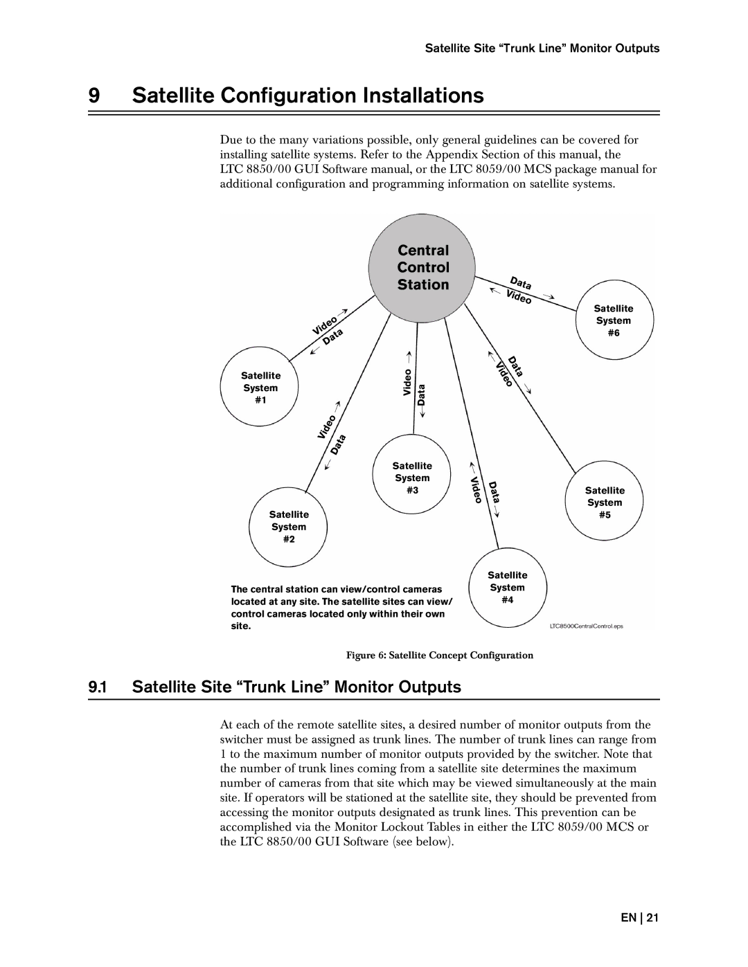
The central station can view/control cameras located at any site. The satellite sites can view/ control cameras located only within their own site.
Data
Video
D
V a i t d a
e
o
V | D |
i | |
d | a |
e | t |
o | a |
Satellite
System
#4
Satellite
System
#6
Satellite
System
#5
Figure 6: Satellite Concept Configuration
9.1Satellite Site “Trunk Line” Monitor Outputs
At each of the remote satellite sites, a desired number of monitor outputs from the switcher must be assigned as trunk lines. The number of trunk lines can range from 1 to the maximum number of monitor outputs provided by the switcher. Note that the number of trunk lines coming from a satellite site determines the maximum number of cameras from that site which may be viewed simultaneously at the main site. If operators will be stationed at the satellite site, they should be prevented from accessing the monitor outputs designated as trunk lines. This prevention can be accomplished via the Monitor Lockout Tables in either the LTC 8059/00 MCS or the LTC 8850/00 GUI Software (see below).
EN 21