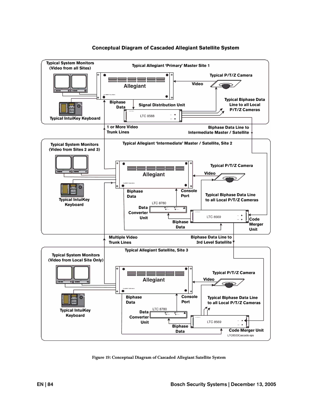
Conceptual Diagram of Cascaded Allegiant Satellite System
Typical System Monitors |
| Typical Allegiant ‘Primary’ Master Site 1 | ||
(Video from all Sites) |
| |||
|
|
|
| |
|
|
|
| Typical P/T/Z Camera |
|
|
| Video |
|
| Biphase |
|
| Typical Biphase Data |
| Signal Distribution Unit | Line to all Local | ||
| Data | |||
|
|
| P/T/Z Cameras | |
|
|
|
| |
Typical IntuiKey Keyboard |
|
|
|
|
| 1 or More Video |
| Biphase Data Line to | |
| Trunk Lines | Intermediate Master / Satellite | ||
Typical System Monitors | Typical Allegiant ‘Intermediate’ Master / Satellite, Site 2 | |||
(Video from Sites 2 and 3) |
|
|
|
|
|
|
|
| Typical P/T/Z Camera |
|
|
|
| Video |
|
| Biphase | Console | Typical Biphase Data Line |
Typical IntuiKey |
| Data | Port | |
|
|
| to all Local P/T/Z Cameras | |
Keyboard |
| Data |
|
|
|
|
|
| |
|
| Converter |
|
|
|
| Unit | Biphase | Code |
|
|
| ||
|
|
| Merger | |
|
|
| Data | |
|
|
| Unit | |
|
|
|
| |
| Multiple Video | Biphase Data Line to | ||
| Trunk Lines | 3rd Level Satellite | ||
| Typical Allegiant Satellite, Site 3 |
| ||
Typical System Monitors |
|
|
|
|
(Video from Local Site Only) |
|
|
|
|
|
|
|
| Typical P/T/Z Camera |
|
|
|
| Video |
|
| Biphase | Console | Typical Biphase Data Line |
|
| Data | Port | to all Local P/T/Z Cameras |
Typical IntuiKey |
| Data |
|
|
Keyboard |
|
|
| |
| Converter |
|
| |
|
|
|
| |
|
| Unit | Biphase |
|
|
|
| Code Merger Unit | |
|
|
| Data | |
Figure 19: Conceptual Diagram of Cascaded Allegiant Satellite System
EN 84 | Bosch Security Systems December 13, 2005 |
