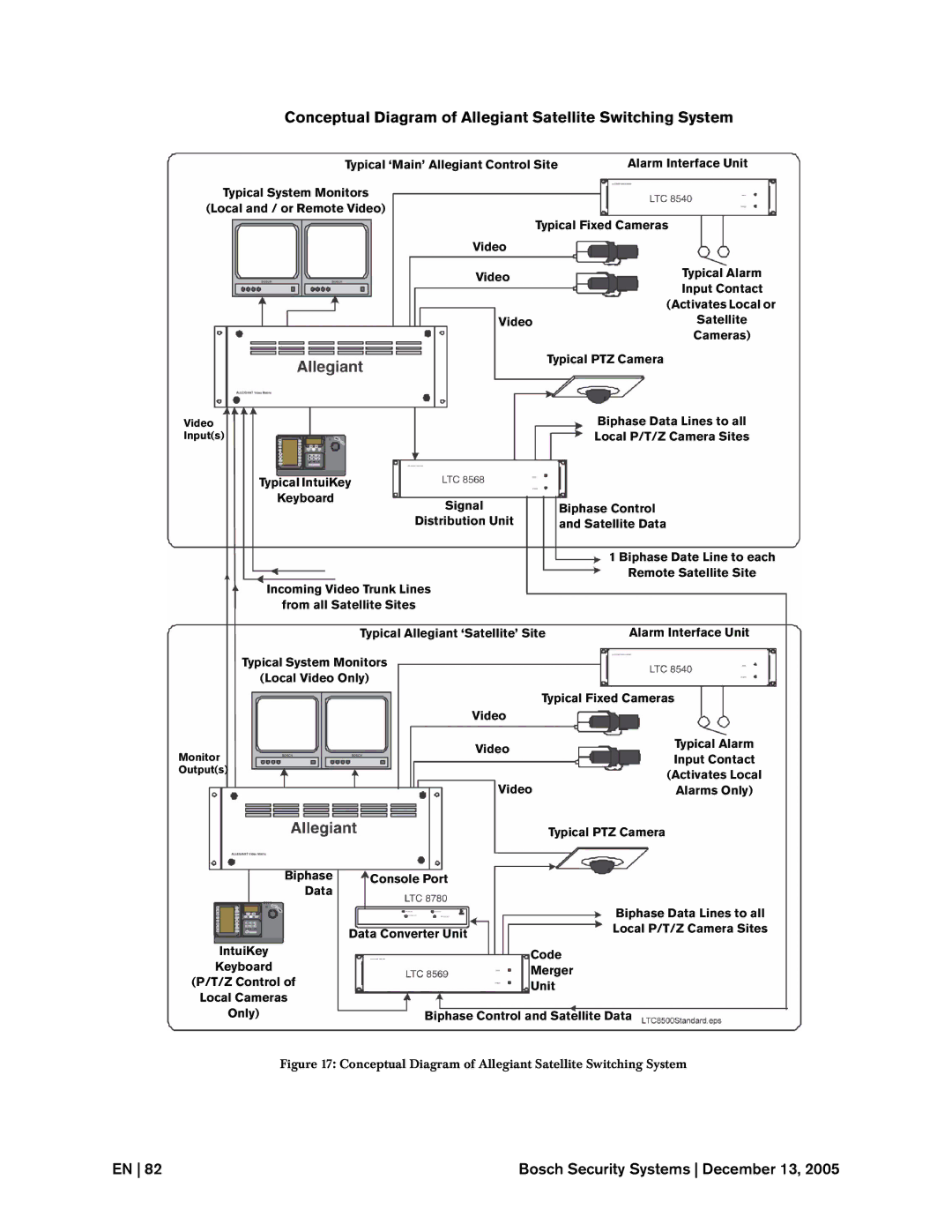
Conceptual Diagram of Allegiant Satellite Switching System
Typical ‘Main’ Allegiant Control Site | Alarm Interface Unit |
Typical System Monitors
(Local and / or Remote Video)
Typical Fixed Cameras
Video
Video | Typical Alarm | |
Input Contact | ||
| ||
| (Activates Local or | |
Video | Satellite | |
| Cameras) | |
| Typical PTZ Camera |
Video Input(s)
Typical IntuiKey
Keyboard
Signal
Distribution Unit
Incoming Video Trunk Lines
from all Satellite Sites
Biphase Data Lines to all
Local P/T/Z Camera Sites
Biphase Control
and Satellite Data
1 Biphase Date Line to each
Remote Satellite Site
Typical Allegiant ‘Satellite’ Site | Alarm Interface Unit |
Typical System Monitors
(Local Video Only)
Typical Fixed Cameras
Video
Monitor
Output(s)
Biphase | Console Port |
Data |
|
| Data Converter Unit |
IntuiKey |
|
Keyboard |
|
(P/T/Z Control of |
|
Local Cameras |
|
Video | Typical Alarm | |
Input Contact | ||
| ||
| (Activates Local | |
Video | Alarms Only) | |
| Typical PTZ Camera |
Biphase Data Lines to all
Local P/T/Z Camera Sites
Code
Merger
Unit
Only) | Biphase Control and Satellite Data |
Figure 17: Conceptual Diagram of Allegiant Satellite Switching System
EN 82 | Bosch Security Systems December 13, 2005 |