Video Output Modules
7.3Video Output Modules
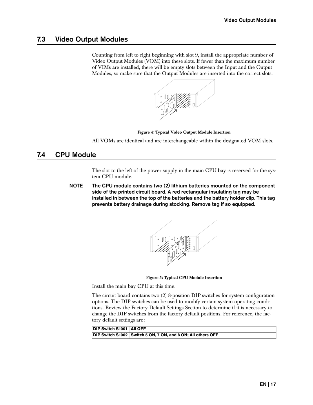
Counting from left to right beginning with slot 9, install the appropriate number of Video Output Modules (VOM) into these slots. If fewer than the maximum number of VIMs are installed, there will be empty slots between the Input and the Output Modules, so make sure that the Output Modules are inserted into the correct slots.
Figure 4: Typical Video Output Module Insertion
All VOMs are identical and are interchangeable within the designated VOM slots.
7.4CPU Module
| The slot to the left of the power supply in the main CPU bay is reserved for the sys- | ||
| tem CPU module. | ||
NOTE | The CPU module contains two (2) lithium batteries mounted on the component | ||
| side of the printed circuit board. A red rectangular insulating tag may be | ||
| installed in between the top of the batteries and the battery holder clip. This tag | ||
| prevents battery drainage during stocking. Remove tag if so equipped. | ||
|
|
|
|
|
|
|
|
Figure 5: Typical CPU Module Insertion
Install the main bay CPU at this time.
The circuit board contains two (2)
DIP Switch S1001 All OFF
DIP Switch S1002 Switch 5 ON, 7 ON, and 8 ON; All others OFF
EN 17