Manuals
/
Bosch Appliances
/
Household Appliance
/
Home Security System
Bosch Appliances
instruction manual
LTC 8500 Character ROM Table
Models:
8500
LTC
1
79
104
104
Download
104 pages
32.59 Kb
76
77
78
79
80
81
82
83
Troubleshooting
Install
Parts list
Error codes
Alarm Information
Factory Default Settings
Maintenance
System Accessory Components
System Commands
Procedures not covered
Page 79
Image 79
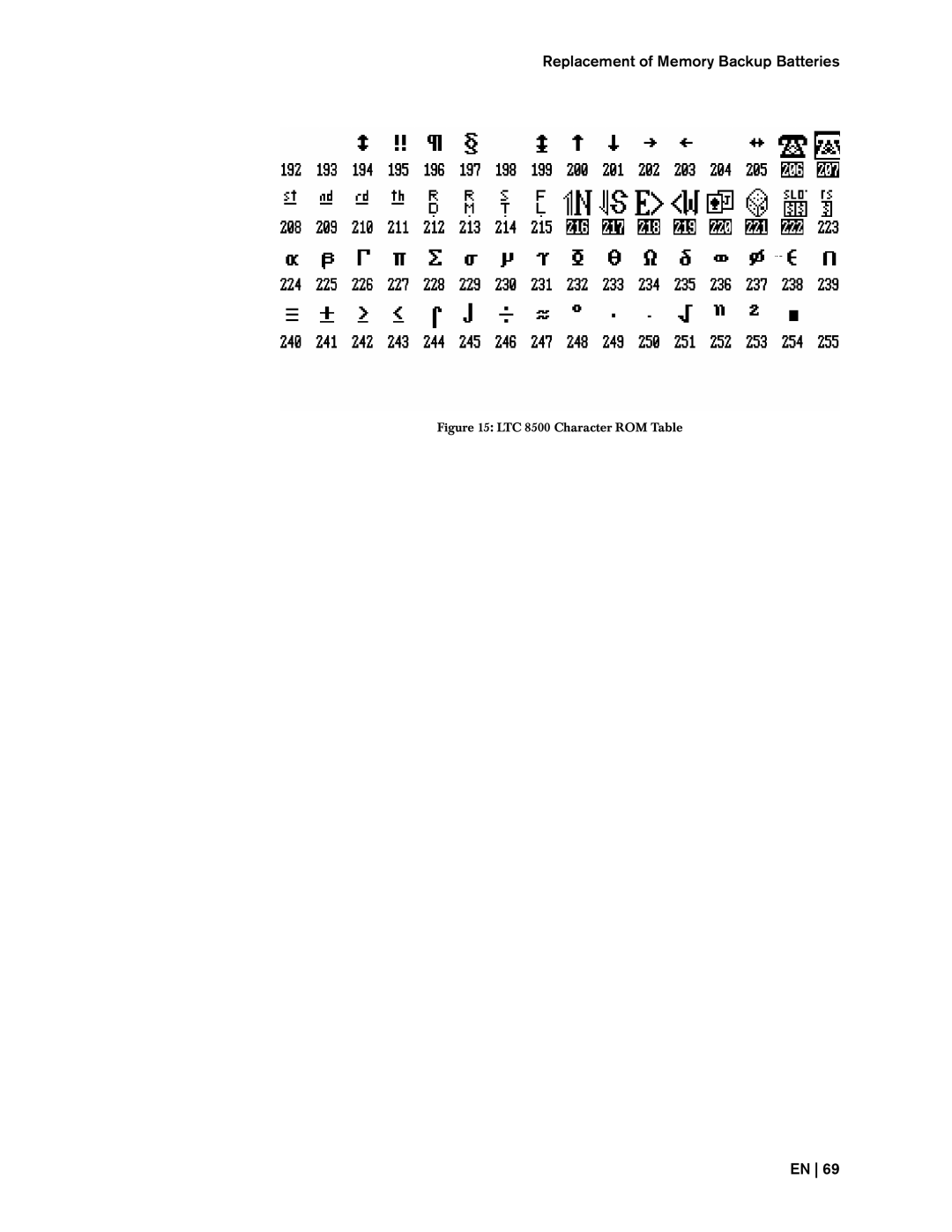
Replacement of Memory Backup Batteries
Figure 15: LTC 8500 Character ROM Table
EN 69
Page 78
Page 80
Page 79
Image 79
Page 78
Page 80
Contents
LTC 8500 Series
Bosch
Bosch Security Systems December 13
Important Safeguards
For Outdoor Product
For Indoor Product
For Rack-mount Product
Sicherheitshinweise
Sécurité
Precauciones de Seguridad
Sicurezza
Veiligheidsmaatregelen Medidas de Segurança
Page
Bosch Security Systems December 13
Page
Bosch Security Systems December 13
Unpacking
Parts List
Qty
USA
Service
Description
Bosch Security Systems December 13
Allegiant Feature Summary Table
Bosch Security Systems December 13
LTC 8501 Series Systems
System Components
LTC 8501 Series Systems
IntuiKey Series KBD-Universal Keyboard
System Accessory Components
LTC 8540/00 Alarm Interface Unit
LTC 8568 and LTC 8768 Signal Distribution Units
LTC 8560 and LTC 8561 Series Receiver/Driver Units
LTC 8555 Series Keyboards
LTC 8558/00 Keyboard Extension Cable
LTC 8557 Series Keyboard Extension Kits
LTC 8713 Alarm Port Expander Units
LTC 8770 Switcher Follower Series
LTC 8712 Series Console Port Expander Units
LTC 8785 Series Code Converters
LTC 8780 Series Data Converter Units
LTC 8781 Series Data Converter Units
LTC 8016/90 Bilinx Data Interface Unit
Integration Server
LTC 8059/00 Master Control Software
LTC 8850/00 Windows Based Graphical User Interface Software
SFT-INTSRV Allegiant Integration Software
Allegiant Satellite Software Development Kit
LTC 8506/00 PC-to-Console Port RS-232 Cable
LTC 8506/00 PC-to-Console Port RS-232 Cable
Logging Printer
LTC 8500 Series Video Switching Configuration
Tion provided at the end of this manual
Data
Main CPU Bay Installation
Installation Procedure
Video Input Modules
CPU Module
Video Output Modules
Video Output Modules
Monitor Output Video Connections
Camera and Monitor Video Connections
Termination Practices
LTC 8500 Series Video Terminations
Procedures not covered
Optional Accessories Installation
General Accessory Installation
Logging Printer Option Installation
Computer
Computer Interface Installation
Satellite Site Trunk Line Monitor Outputs
Satellite Configuration Installations
Satellite Site Trunk Line Monitor Outputs
Control Data Lines in Satellite Systems
Main Site Trunk Line Video Inputs
Satellite Site Programming Requirements
Main Site Programming Requirements
Main Site Programming Requirements
Ming of the main site via a system keyboard
Page
Alarm Inputs in Satellite Systems
Alarm Inputs in Satellite Systems
Feature Selection
LTC 8501 Series Rear Panel
Main Power Connections
Monitor Message
Video Monitor Display
Time / Date
Monitor Title/System Status Display
System Status Display
Monitor Title/System Status Display
Bosch Security Systems December 13
User Selectable DIP Switch Settings for Main CPU Bay
Factory Default Settings
User Selectable DIP Switch Settings for Main CPU Bay
Upper CPU DIP Switch S1001
Lower CPU DIP Switch S1002
Keyboard model Supported protocols
Boards are initially logged-off
Drivers without using an LTC 8785 Series Code Converter unit
Settings Console Port Printer Port Alarm Port Keyboard Ports
User Priority Levels
User Information
User Priority Access Table
User Priority Access Table
System Function
Sequence and Display Alarm Response Mode
Alarm Information
Basic Alarm Response Mode
Auto Build Alarm Response Mode
Sample Alarm Responses
Alarm Activated Pre-position
Alarm Activated Pre-position
None
Alarm Relay Response
Alarm Relay Response
IntuiKey button text
System Commands
Keyboard Log-in Procedure
Keyboard Operation
Controlling Camera Movement
Switcher Commands
Recalling a Camera Pre-position Scene
Alarm activations are defaulted to call preposition scene
Lock or Unlock Control of a Monitor
Recording a Camera Pre-position Scene
Arm/Disarm Individual Alarms
Alarm Commands
Alarm Commands
Arm/Disarm Monitor
Arm/Disarm All Alarms
Alarms Acknowledgement
Sequence Control
Sequence Control
Run a Sequence
Stop a Running Sequence
Controlling Sequence Direction
Programming a Simple Camera Sequence
Sequence Programming
Sequence Programming
Sequence Function Summary
Key Description
Camera Monitor Dwell
Programming a SalvoSwitching Camera Sequence
General Information
Keyboard User Functions
General Information
These functions are listed in the table shown below
Key
User Function 1 Local Keyboard Test
User Function 6 Select Monitor Display Option
User Function 4 Adjust Position of Monitor Overlay
User Function 2 Show Keyboard Port Number
User Function 3 Select Keyboard Beeper ON/OFF
User Function 9 Set Camera ID
User Function 10 Change User Password
User Function 7 Set Time
User Function 8 Set Date
User Function 11 Select Time / Date Format
User Function 12 Default All Monitor Overlays
User Function 13 Print System Configuration Tables
User Function 16 Time Event Enable/Disable
User Function 20 Select Printer Verbosity
User Function 19 Select Alarm Response
User Function 21 Designate Alarm Monitor Type
User Function 18 Print Sequence
User Function 26 Set Display Option On All Monitors
User Function 23 Display CPU Software Version Number
User Function 24 Set Positions on All Monitor Displays
User Function 25 Set Brightness on All Monitor Displays
User Function 30 Set Console RS-232 Parameters
User Function 29 Reset RS-232 Parameters to Default
User Function 32 Set Alarm RS-232 Parameters
User Function 28 Select Console Log-in
User Function 35 Controllable Cameras
User Function 34 Camera Indicator
User Function 37 R/D Address Mode
User Function 38 Printer Port Mode
General Information
User Function 43 CPU Battery Status
User Function 42 Keyboard Log-in Auto-off Mode
User Function 99 User Function Index
AC Line Voltage Input Selection
Maintenance Information
Cleaning the Keyboard
Cleaning the Keyboard
Power Supply Fuse Replacement
AC Line Fuse Replacement
Replacement of Memory Backup Batteries
Replacement of Memory Backup Batteries
Character ROM Tables for LTC
LTC 8500 Character ROM Table
Error Messages
Replacement of Memory Backup Batteries
Bosch Security Systems December 13
Main Bay Checkout
Troubleshooting Guide
Main Bay Checkout
Keyboard Checkout
Video Monitor Display Checkout
No Alarm Response
Remote Receiver/Driver Functions Inoperative
CPU Software Version Numbers
CPU Software Version Numbers
Glossary of Terms
CPU Software Version Numbers
Appendix a Satellite Systems
Allegiant Satellite Concepts
Model No Maximum Number System Cameras
CPU Software Version Numbers
Conceptual Diagram of Allegiant Satellite Switching System
Conceptual Diagram of Allegiant Satellite Switching System
Conceptual Diagram of Dual Master Allegiant Satellite System
Conceptual Diagram of Cascaded Allegiant Satellite System
Conceptual Diagram of Cascaded Allegiant Satellite System
Main BAY Hardware Installation
Appendix B Installation Checklists
Keyboards
Alarm Interface Unit
Appendix C Quick Reference Cable Interconnections
Main Bay Video
Receiver/Drivers
Signal Distribution Unit
Keyboard RS-485 Ports
Main Bay Rear Panel Connector Pin-outs and Cable Pin-out
Alarm Port RS-232 Pin-outs
Console Port RS-232 Pin-outs
Comm Port 1 and Comm Port
CPU Software Version Numbers Code Port Pin-outs
CTS RTS
Page
Bosch Security Systems December 13
Page
Europe, Middle East, Africa Asia-Pacific
Top
Page
Image
Contents