![]() BM 2610012089
BM 2610012089
Basic Saw Operations
Miter Detent Override
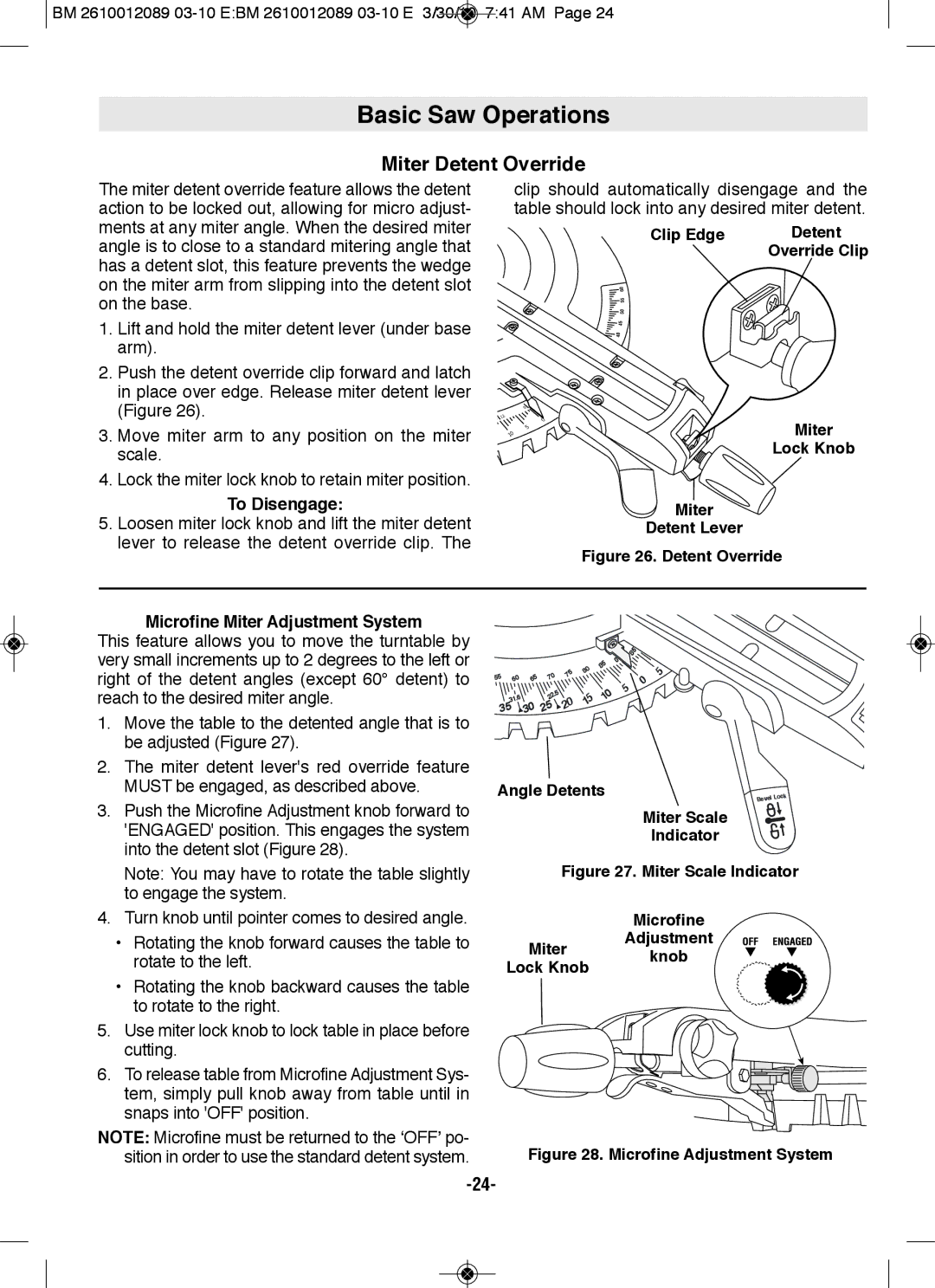
The miter detent override feature allows the detent action to be locked out, allowing for micro adjust- ments at any miter angle. When the desired miter angle is to close to a standard mitering angle that has a detent slot, this feature prevents the wedge on the miter arm from slipping into the detent slot on the base.
1.Lift and hold the miter detent lever (under base arm).
2.Push the detent override clip forward and latch in place over edge. Release miter detent lever (Figure 26).
3.Move miter arm to any position on the miter scale.
4.Lock the miter lock knob to retain miter position.
To Disengage:
5.Loosen miter lock knob and lift the miter detent lever to release the detent override clip. The
clip should automatically disengage and the table should lock into any desired miter detent.
| Clip Edge | Detent |
|
| Override Clip |
| 60 |
|
| 55 |
|
| 50 |
|
| 45 |
|
| 40 |
|
| 0 |
|
2 |
|
|
1 | 0 |
|
| Miter | |
| 10 | |
| 5 |
|
lock Knob
Miter
Detent lever
figure 26. Detent Override
Microfine Miter Adjustment System
This feature allows you to move the turntable by very small increments up to 2 degrees to the left or right of the detent angles (except 60° detent) to reach to the desired miter angle.
1.Move the table to the detented angle that is to be adjusted (Figure 27).
2.The miter detent lever's red override feature MUST be engaged, as described above.
3.Push the Microfine Adjustment knob forward to 'ENGAGED' position. This engages the system into the detent slot (Figure 28).
Note: You may have to rotate the table slightly to engage the system.
4.Turn knob until pointer comes to desired angle.
•Rotating the knob forward causes the table to rotate to the left.
•Rotating the knob backward causes the table to rotate to the right.
5.Use miter lock knob to lock table in place before cutting.
6.To release table from Microfine Adjustment Sys- tem, simply pull knob away from table until in snaps into 'OFF' position.
NOTE: Microfine must be returned to the ‘OFF’ po- sition in order to use the standard detent system.
|
|
|
|
|
|
| 0 | 85 |
|
|
|
|
|
|
| 85 |
|
| |
|
|
|
|
| 80 |
|
| 5 | |
55 |
|
| 70 | 75 |
|
|
| ||
60 | 65 |
|
|
| 0 | ||||
|
|
|
|
| |||||
|
|
|
|
|
|
| 5 |
| |
|
|
| .5 |
|
| 10 |
|
| |
| 31 |
| 22 |
|
|
|
|
| |
| .6 |
| 20 | 15 |
|
|
|
| |
35 | 30 | 25 |
|
|
|
| |||
|
|
|
|
|
| ||||
Angle Detents | Bevel | Lock |
|
|
Miter Scale
Indicator
