![]() BM 2610012089
BM 2610012089
Adjustments
Checking left 45°
Bevel Stop
1.Lower head assembly and engage head assem- bly lock pin.
2.Slide head assembly completely to the back and tighten the rail lock knob.
3.Rotate table to the 0° miter position.
4.Pull up bevel lock lever to unlock bevel.
5.Move bevel range selector knob to
6.Tilt the saw assembly to the left, then rotate saw assembly to the right until you feel the stop in the 45° left position. This is where the saw is cur- rently set for the 45° left bevel cut.
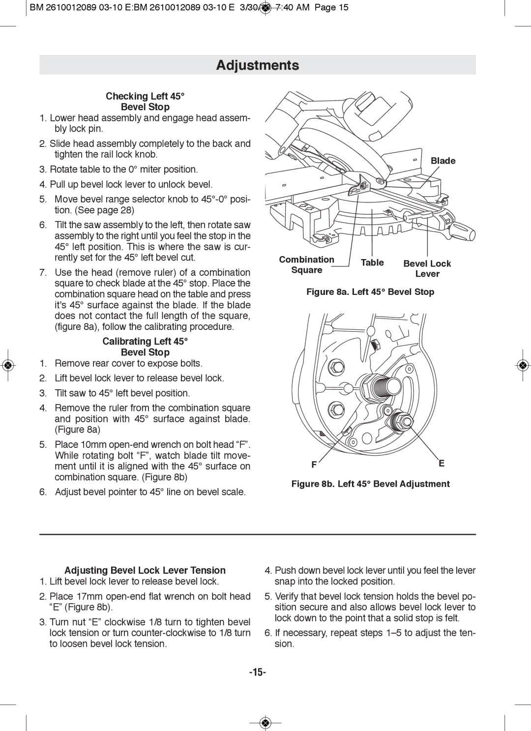
7.Use the head (remove ruler) of a combination square to check blade at the 45° stop. Place the combination square head on the table and press it’s 45° surface against the blade. If the blade does not contact the full length of the square, (figure 8a), follow the calibrating procedure.
Calibrating left 45°
Bevel Stop
1.Remove rear cover to expose bolts.
2.Lift bevel lock lever to release bevel lock.
3.Tilt saw to 45° left bevel position.
4.Remove the ruler from the combination square and position with 45° surface against blade. (Figure 8a)
5.Place 10mm
6.Adjust bevel pointer to 45° line on bevel scale.
Blade
Combination | Table |
|
| |
Bevel lock | ||||
Square | ||||
| lever | |||
|
| |||
figure 8a. left 45° Bevel Stop
f | E |
figure 8b. left 45° Bevel Adjustment
Adjusting Bevel lock lever Tension
1.Lift bevel lock lever to release bevel lock.
2.Place 17mm
3.Turn nut “E” clockwise 1/8 turn to tighten bevel lock tension or turn
4.Push down bevel lock lever until you feel the lever snap into the locked position.
5.Verify that bevel lock tension holds the bevel po- sition secure and also allows bevel lock lever to lock down to the point that a solid stop is felt.
6.If necessary, repeat steps