![]() BM 2610012089
BM 2610012089
Bevel Range Selection | |
Choose the desired bevel range | |
using the bevel range selector | left |
| |
knob (Figure 33). |
|
To operate in Bevel Range - 45° left to 0° (This left bevel range is the default setting)
a. Extend left sliding fence to clear saw assembly and
b. Lift bevel lock lever to release bevel lock (Fig. 33).
c. Grasp the front carry handle with right hand and tilt saw head to angle desired (Figure 34).
d. Push down bevel lock lever until you feel the lever snap into the locked position.
To operate in Bevel Range 0° | |
to 45° Right: | |
a. Extend right sliding fence to | Right |
clear saw assembly and re- | |
lock (Figure 2). |
|
b. Lift bevel lock lever to release bevel lock (Fig. 33).
c. Standing on right side of saw, grasp the front car- ring handle with right hand and tilt saw head slightly to the left while rotating the bevel range selector knob with left hand to
d. Tilt saw head to desired right bevel angle, up to the 45° stop.
e.Push down bevel lock lever until you feel the lever snap into the locked position.
NOTE: When the saw assembly is tilted back left past 0°, the bevel control knob will snap back to the default bevel range 1. This is designed to regain the
To operate in Bevel Range 47° |
| |
Max | ||
left to 46° Right: | ||
This full capacity bevel range set- | Range | |
ting overrides all preset stops |
| |
|
and allows for cutting at bevel angles beyond the normal 45° on either side.
a.Move left or right sliding fence to clear saw as- sembly and
b.Lift bevel lock lever to release bevel lock (Fig. 33).
c.Standing on right side of saw, grasp the front carring handle with right hand and tilt saw head slightly to the left while rotating the bevel range selector knob with left hand to “Max Range” (Figure 34).
d.Tilted saw head to any angle from 47° left to 46° right.
e.Push down bevel lock lever until you feel the lever snap into the locked position.
follow these instructions for making your bevel cut:
1.Extend the base extensions on the side on which the cut will be made. (See Sliding Fence and Base Extension on page 25).
2.Properly position workpiece. Make sure work piece is clamped firmly against the table and the fence.
NOTE: Use clamping position that does not in- terfere with operation.
3.Before turning the saw on, practice the cutting action to make sure the fence clears the guards and adjust as necessary.
4.Follow the procedures for either a chop cut or slide cut (see page 26).
5.Wait until blade comes to a complete stop before returning head assembly to the raised position and/or removing workpiece.
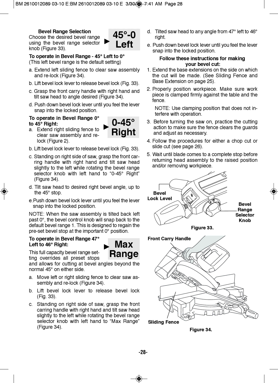
Bevel
lock level
Bevel Range Selector
Knob
figure 33.
front Carry Handle
Sliding fence
figure 34.