Connecting devices and completing the setup | 2 |
EZSwitchSetup uses these values to verify that all your current and planned devices are properly connected for the zoning scheme that will be created. Note that Typical Zoning ensures that every connected host device will be able to communicate with every connected storage device.
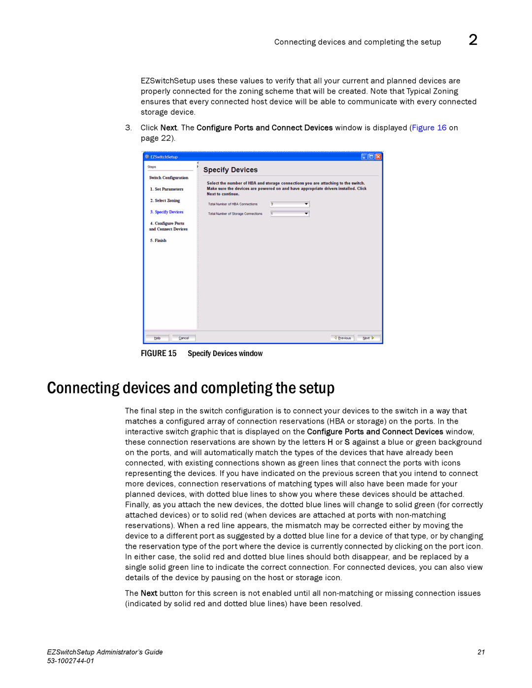
3.Click Next. The Configure Ports and Connect Devices window is displayed (Figure 16 on page 22).
FIGURE 15 Specify Devices window
Connecting devices and completing the setup
The final step in the switch configuration is to connect your devices to the switch in a way that matches a configured array of connection reservations (HBA or storage) on the ports. In the interactive switch graphic that is displayed on the Configure Ports and Connect Devices window, these connection reservations are shown by the letters H or S against a blue or green background on the ports, and will automatically match the types of the devices that have already been connected, with existing connections shown as green lines that connect the ports with icons representing the devices. If you have indicated on the previous screen that you intend to connect more devices, connection reservations of matching types will also have been made for your planned devices, with dotted blue lines to show you where these devices should be attached. Finally, as you attach the new devices, the dotted blue lines will change to solid green (for correctly attached devices) or to solid red (when devices are attached at ports with
The Next button for this screen is not enabled until all
EZSwitchSetup Administrator’s Guide | 21 |
|