Put the side cover back on.
Reconnect any additional interface cables that you removed.
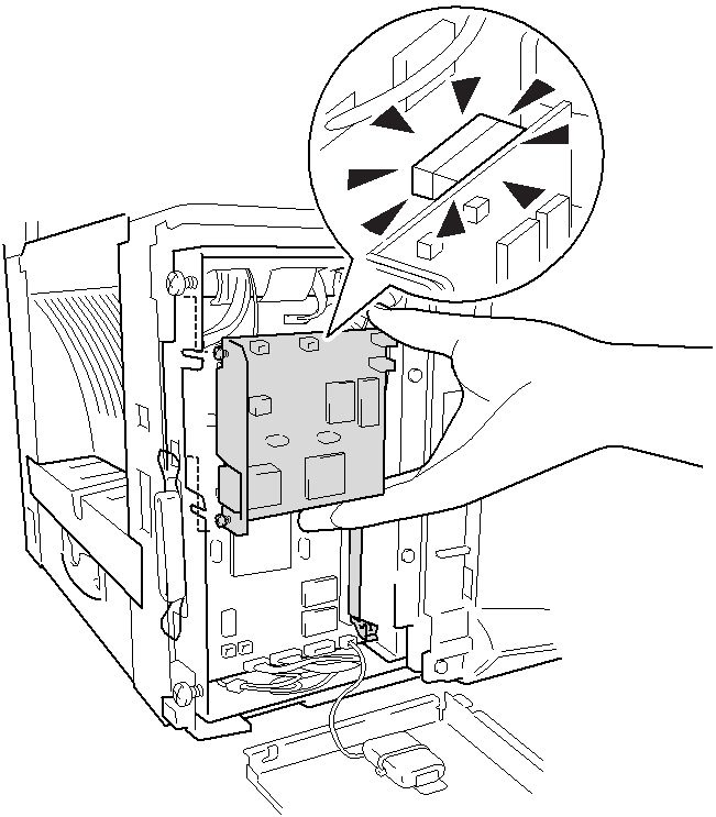
4 Plug the
5 Put the metal shield plate back on and secure it with the two screws.
6
7
8 Reconnect the power cable and then turn on the MFC power switch.
9
10
Reconnect the telephone line cord and handset curled cord.
Press the Test switch and print a network configuration page. (See Test switch on page
OPTIONAL ACCESSORIES 13 - 7