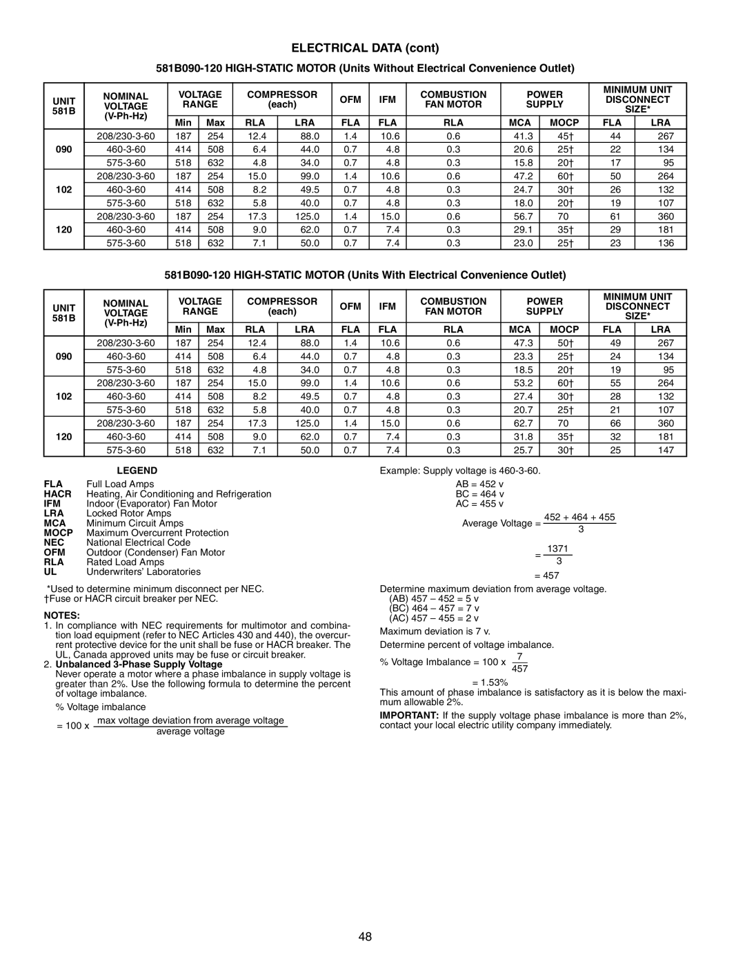
581B specifications
The Bryant 581B is an innovative and highly efficient gas furnace that stands out in the HVAC market for its remarkable performance, reliability, and advanced features. Designed to provide optimal heating comfort, the Bryant 581B is perfect for homeowners seeking both quality and energy efficiency.One of the main features of the Bryant 581B is its impressive Annual Fuel Utilization Efficiency (AFUE) rating. With an AFUE rating of up to 80%, this gas furnace maximizes energy usage, ensuring that a significant portion of the fuel is converted into heat for your home. This efficiency not only translates into lower energy bills but also reduces the carbon footprint, making it an environmentally friendly choice.
The furnace is equipped with a multi-speed blower motor that enhances comfort by providing consistent airflow throughout the home. This technology adjusts to different heating demands, ensuring that every room reaches the desired temperature without the discomfort of hot or cold spots. The quiet operation of the blower motor also adds to the overall comfort, creating a peaceful home environment.
Another notable characteristic of the Bryant 581B is its durable construction. It features a robust heat exchanger built from high-quality materials, designed to withstand the rigors of daily use. The compact design of the furnace allows it to fit seamlessly into various spaces, making it an ideal choice for both new installations and replacement projects.
The Bryant 581B also comes with advanced safety features, including a self-diagnostic control board that monitors the system's performance. This feature allows for easy troubleshooting and maintenance, prolonging the life of the furnace. Additionally, the furnace is equipped with an induced draft blower that enhances venting efficiency and safety by ensuring that combustion gases are safely expelled from the home.
For homeowners looking for enhanced control, the Bryant 581B is compatible with a range of smart thermostats, providing the ability to monitor and adjust heating settings remotely. This integration with smart technology ensures that homeowners can maintain their desired comfort levels while maximizing efficiency.
In conclusion, the Bryant 581B gas furnace is a top-tier option that combines efficiency, durability, and modern technology. With its high AFUE rating, multi-speed blower, and advanced safety features, it promises to deliver unparalleled comfort and peace of mind for years to come. Whether for a new build or an upgrade, the Bryant 581B is an investment that pays off in both comfort and savings.

