Removing the Chassis Cover
C.2.1 Setting the Mode Switch
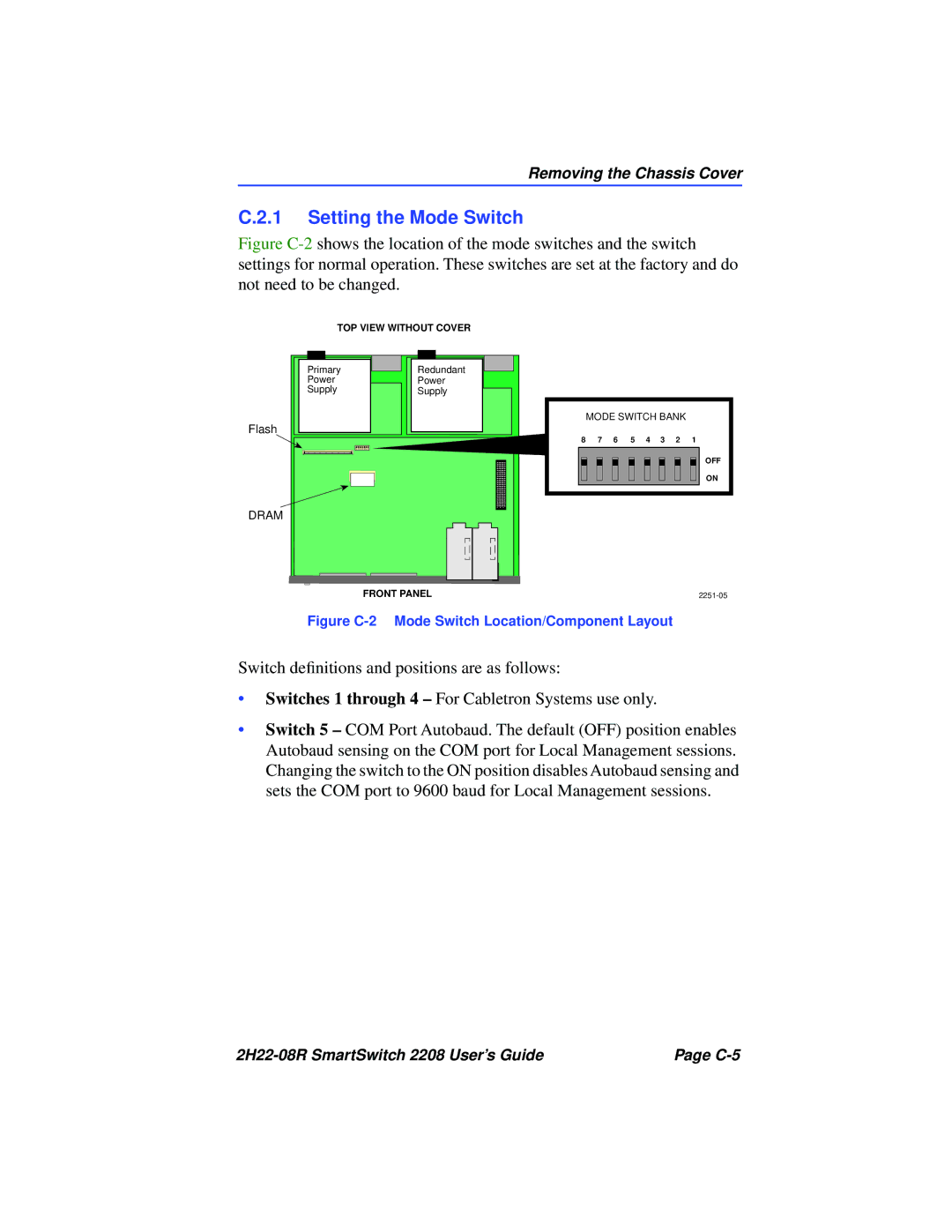
Figure C-2 shows the location of the mode switches and the switch settings for normal operation. These switches are set at the factory and do not need to be changed.
TOP VIEW WITHOUT COVER
Primary
Power
Supply
Redundant
Power
Supply
Flash
DRAM
MODE SWITCH BANK
8 7 6 5 4 3 2 1
OFF
ON
FRONT PANEL |
Figure C-2 Mode Switch Location/Component Layout
Switch definitions and positions are as follows:
•Switches 1 through 4 – For Cabletron Systems use only.
•Switch 5 – COM Port Autobaud. The default (OFF) position enables Autobaud sensing on the COM port for Local Management sessions. Changing the switch to the ON position disables Autobaud sensing and sets the COM port to 9600 baud for Local Management sessions.
Page |