Connecting to the Network
Connect an
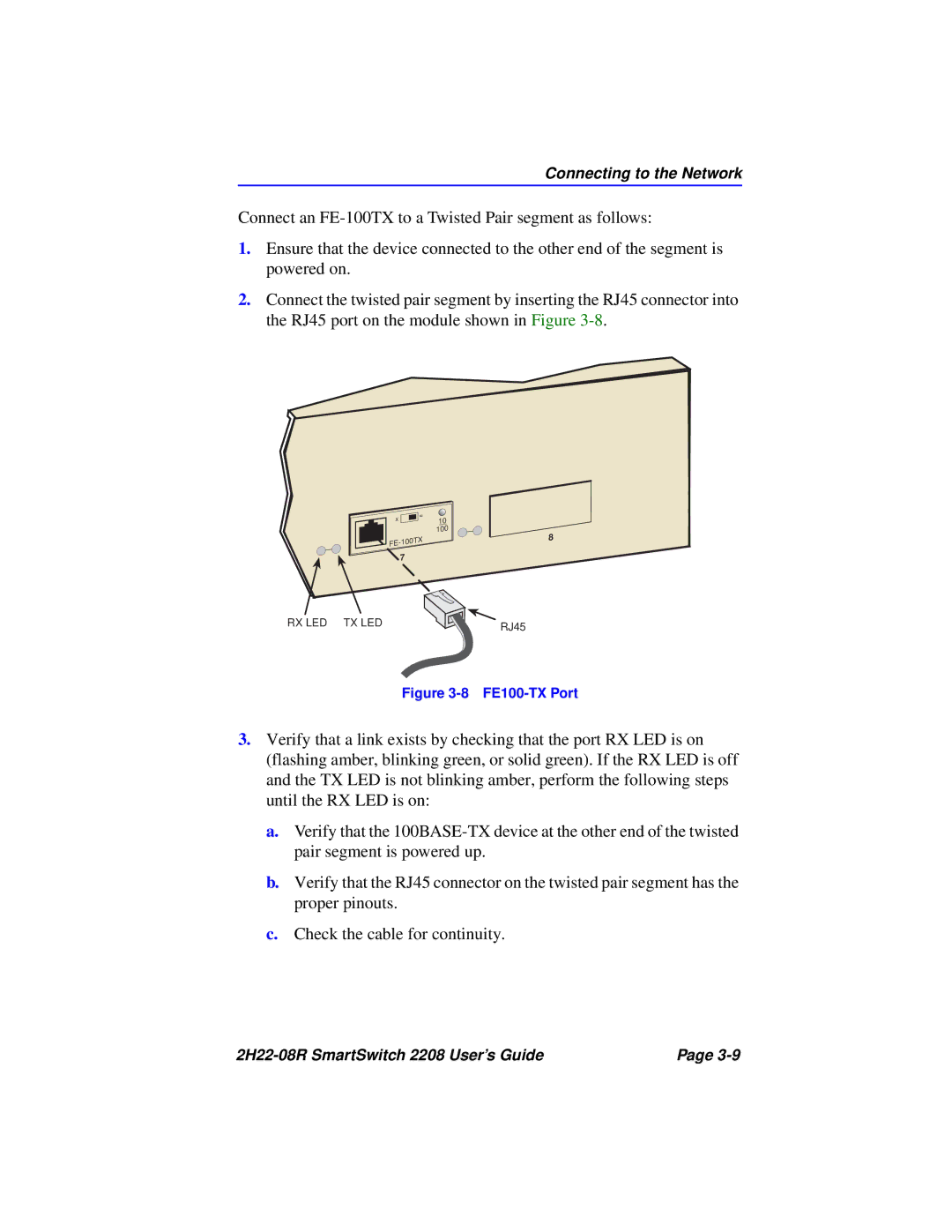
1.Ensure that the device connected to the other end of the segment is powered on.
2.Connect the twisted pair segment by inserting the RJ45 connector into the RJ45 port on the module shown in Figure
x | = |
| |
| 7 |
10 100
8
RX LED TX LED | RJ45 |
|
Figure 3-8 FE100-TX Port
3.Verify that a link exists by checking that the port RX LED is on (flashing amber, blinking green, or solid green). If the RX LED is off and the TX LED is not blinking amber, perform the following steps until the RX LED is on:
a.Verify that the
b.Verify that the RJ45 connector on the twisted pair segment has the proper pinouts.
c.Check the cable for continuity.
| Page |