Installing Optional Fast Ethernet Interface Modules
C.3 INSTALLING OPTIONAL FAST ETHERNET INTERFACE MODULES
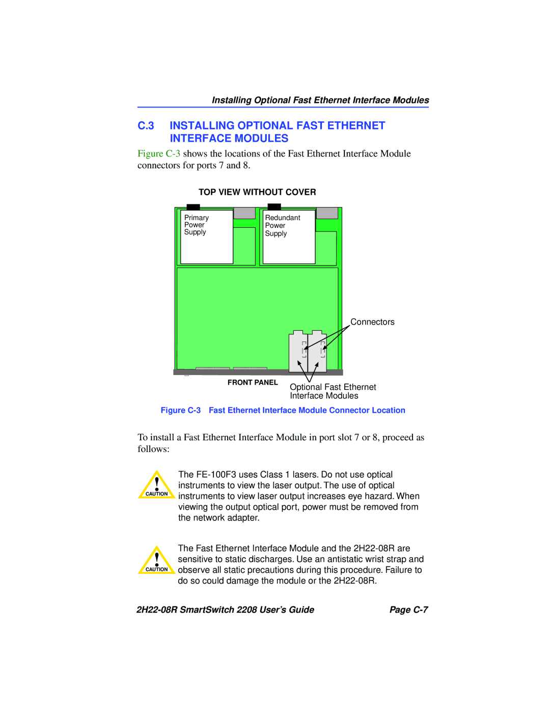
Figure C-3 shows the locations of the Fast Ethernet Interface Module connectors for ports 7 and 8.
TOP VIEW WITHOUT COVER
Primary
Power
Supply
Redundant
Power
Supply
FRONT PANEL
Connectors
Optional Fast Ethernet Interface Modules
Figure C-3 Fast Ethernet Interface Module Connector Location
To install a Fast Ethernet Interface Module in port slot 7 or 8, proceed as follows:
The
!instruments to view the laser output. The use of optical
CAUTION | instruments to view laser output increases eye hazard. When |
| |
| viewing the output optical port, power must be removed from |
| the network adapter. |
!
CAUTION
The Fast Ethernet Interface Module and the
| Page |