SmartSwitch Router User Reference Manual
9032578-05
Disclaimer
Copyright
Changes
Trademarks
Regulatory Compliance Information
Regulatory Compliance Statements
Industry Canada Compliance Statement
Vcci Compliance Statement
Safety Information Class 1 Laser Transceivers
Laser Radiation and Connectors
Cabletron Systems, Inc Program License Agreement
SmartSwitch Router User Reference Manual Vii
Viii SmartSwitch Router User Reference Manual
SmartSwitch Router User Reference Manual
Cabletron Systems Limited Program License Agreement
Cabletron Systems Limited Program License Agreement
Declaration of Conformity Addendum
Contents
SmartTRUNK Configuration Guide
Dhcp Configuration Guide
Vrrp Configuration Guide
111
Routing Policy Configuration Guide 161
160
197
Network Address Translation Configuration Guide
Firewall Load Balancing 214 Monitoring IP Policies 215
249
Security Configuration Guide 275
QoS & Layer-2/Layer-3/Layer-4 Flow Overview 291
309
Lfap Configuration Guide 329
357
Contents Xxvi SmartSwitch Router User Reference Manual
Document Conventions
About This Manual
Related Documentation
For Information About See
Keywords or arguments separated by vertical bars indicate a
Keywords and arguments within a set of square brackets are
Optional
Choice. Select one keyword or argument
Configuration Files
Chapter Introduction
User Mode
Using the Command Line Interface
Command Modes
Enable Mode
Boot Prom Mode
Getting Help with CLI Commands
Configure Mode
CLI completes the command as follows
Line Editing Commands
CLI Line Editing Commands
Word-backward command
Next command from history buffer
Previous command from history buffer
Show all commands currently stored in the history buffer
Displaying and Changing Configuration Information
Commands to Display and Change Configuration Information
Erase startup
Task Command
Erase scratchpad
Save active
Port Numbers for Line Cards
Port Names
Each port in the SSR is referred to in the following manner
Line Card Port Number Arrangement Left to Right
Base LLX Quad Serial WAN
Hssi WAN
Chapter Hot Swapping Line Cards Control Modules
Hot Swapping Overview
Hot Swapping Line Cards
Deactivating the Line Card
Hot Swapping One Type of Line Card With Another
Installing a New Line Card
Removing the Line Card
Hot Swapping a Secondary Control Module
Deactivating the Control Module
Installing a Control Module
Removing the Control Module
Hot Swapping a Switching Fabric Module SSR 8600 only
Removing the Switching Fabric Module
Installing a Switching Fabric Module
Page
Spanning Tree Ieee 802.1d
Chapter Bridging Configuration Guide
Bridging Overview
Vlan Overview
Bridging Modes Flow-Based and Address-Based
Protocol-based VLANs
Port-based VLANs
MAC-address-based VLANs
Subnet-based VLANs
Policy-based VLANs
SSR Vlan Support
Multicast-based VLANs
VLANs and the SSR
Access Ports and Trunk Ports 802.1Q support
Ports, VLANs, and L3 Interfaces
Explicit and Implicit VLANs
Configuring SSR Bridging Functions
Configuring Address-based or Flow-based Bridging
SSR
Address-Based Bridge Table Flow-Based Bridge Table
More ports for a particular Vlan
Configuring Spanning Tree
Adjusting Spanning-Tree Parameters
Assigning Port Costs
Setting the Bridge Priority
Setting a Port Priority
Defining the Forward Delay Interval
Adjusting Bridge Protocol Data Unit Bpdu Intervals
Adjusting the Interval between Hello Times
Defining the Maximum Age
Creating a Port or Protocol Based Vlan
Configuring a Port- or Protocol-Based Vlan
Configuring Vlan Trunk Ports
Adding Ports to a Vlan
Configuring VLANs for Bridging
Configuring Layer-2 Filters
Creating an IP or IPX Vlan
Configuration Examples
Monitoring Bridging
Creating a non-IP/non-IPX Vlan
Next, assign ports to the ‘RED’ Vlan
Chapter SmartTRUNK Configuration Guide
Overview
Add Physical Ports to the SmartTRUNK
Configuring SmartTRUNKs
Creating a SmartTRUNK
Monitoring SmartTRUNKs
Specify Traffic Distribution Policy Optional
Example Configurations
St.2 St.4 Router Switch Server
SmartTRUNK Configuration Guide
Page
Virtual Channels
Chapter ATM Configuration Guide
ATM Overview
Atm create vcl port port list
Service Class Definition
Creating a Virtual Channel
Creating a Service Class Definition
Applying a Service Class Definition
Atm set port port list pdh-cell-scramble on off
Cell Scrambling
Enabling Cell Scrambling
Pdh-cell-scramble onoff
Cell Mapping
Selecting the Cell Mapping Format
Atm set port port list cell-mapping direct plcp
Atm set port port list vpi-bits num
Setting the Bit Allocation for VPI
Creating a Non-Zero VPI
Displaying ATM Port Information
Atm show vpl port port list all-ports
Atm show serviceall
Atm show port-settings port list all-ports
B3ZS
G832 is used for E3 framing
Esf indicates extended super frame and is used
For T1 framing
G751 is used for E3 framing
ATM Sample Configuration
Consider the following network configuration
Configuring an Interface on an Ethernet Port
Defining an ATM Service Class
Configuring an IP Route
Applying an ATM Service Class
Configuring an Interface on an ATM Port
Ssr1config# ip add route 11.1.2.0/24 gateway
ATM Sample Configuration
Chapter Packet-over-SONET Configuration Guide
Configuring Packet-over-SONET Links
Configuring IP Interfaces for PoS Links
Configuring Automatic Protection Switching
Configuring Working and Protecting Ports
Specifying Bit Error Rate Thresholds
Monitoring PoS Ports
Specify signal degrade BER
Threshold Specify signal failure BER
Threshold
Following is the configuration for router B
This section shows example configurations for PoS links
Following is the configuration for router a
APS PoS Links Between SSRs
PoS Link Between the SSR and a Cisco Router
Router So.6.1 So-1 40.1.1.1/16
Bridging and Routing Traffic Over a PoS Link
Router So.6.1
Page
Dhcp Overview
Configuration Guide
Chapter
Configuring Client Parameters
Configuring Dhcp
Configuring an IP Address Pool
Client Parameters
Configuring a Static IP Address
Grouping Scopes with a Common Interface
Monitoring the Dhcp Server
Configuring Dhcp Server Parameters
Updating the Lease Database
Define an IP address pool for addresses 10.1.1.10 through
Dhcp Configuration Examples
Define Dhcp network parameters for the scope ‘scope1’
Define a static IP address for
Configuring Secondary Subnets
Secondary Subnets and Directly-Connected Clients
Include ‘scope2’ in the superscope ‘super1’
Interacting with Relay Agents
Define the address pool for ‘scope1’
Page
Unicast Routing Protocols
Chapter IP Routing Configuration Guide
IP Routing Protocols
Configuring IP Interfaces and Parameters
Multicast Routing Protocols
Specifying Ethernet Encapsulation Method
Configuring IP Interfaces to Ports
Configuring IP Interfaces for a Vlan
Configuring Jumbo Frames
To clear the entire ARP table
Configuring Address Resolution Protocol ARP
Configuring ARP Cache Entries
Unresolved MAC Addresses for ARP Entries
Configuring Reverse Address Resolution Protocol Rarp
Configuring Proxy ARP
Specifying IP Interfaces for Rarp
Defining MAC-to-IP Address Mappings
Configuring IP Helper
Configuring DNS Parameters
Configuring IP Services Icmp
Monitoring Rarp
Configuring Direct Broadcast
Configuring Denial of Service DOS
Monitoring IP Parameters
Interface show ip
Configuring Router Discovery
Arp show all
System show dns
Ssrconfig# rdisc add address
To display router discovery information
Ssr# rdisc show all
Assigning IP/IPX Interfaces
Configuring Vrrp
Vrrp Overview
Configuration of Router R1
Basic Vrrp Configuration
Backup
Following is the configuration file for Router R1 in Figure
Following is the configuration file for Router R2 in Figure
Symmetrical Configuration
Configuration for Router R2
Master for VRID=1 Master for VRID=2 Backup for VRID=2
Symmetrical Vrrp Configuration
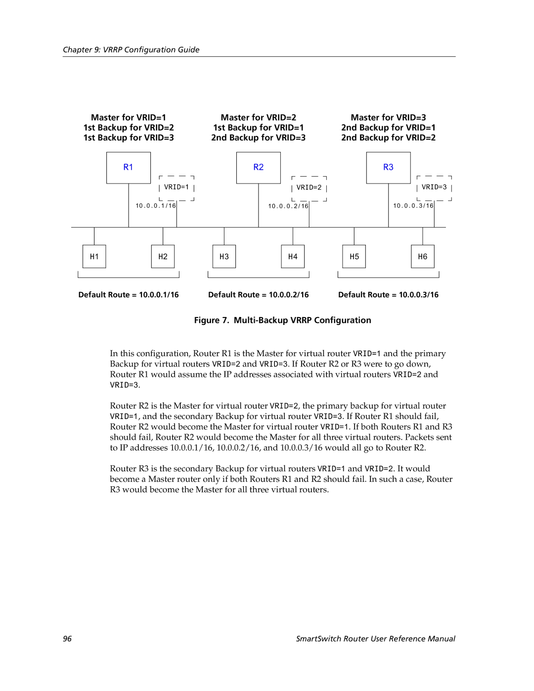
Multi-Backup Configuration
Configuration of Router R2
Multi-Backup Vrrp Configuration
Configuration of Router R1
Virtual Router Default Priority Configured Priority
Following is the configuration file for Router R3 in Figure
Additional Configuration
Configuration of Router R3
Setting Pre-empt Mode
Setting the Backup Priority
Setting the Advertisement Interval
Ip-redundancy trace
Setting an Authentication Key
Monitoring Vrrp
Ip-redundancy show
Ssr# ip-redundancy show vrrp interface int1
Vrrp Configuration Notes
Ssr# ip-redundancy show vrrp 1 interface int1 verbose
104
RIP Overview
Chapter RIP Configuration Guide
Configuring RIP
Enabling and Disabling RIP
Configuring RIP Interfaces
Configuring RIP Parameters
To RIP
Set the authentication method
Characters Set the authentication method
Specify that RIP V2 packets
Monitoring RIP
Configuring RIP Route Preference
Configuring RIP Route Default-Metric
Configuration Example
110
Ospf
Ospf Overview
Configuring Ospf
Ospf Multipath
Ospf Interface Parameters
Configuring Ospf Interface Parameters
Enabling Ospf
Port Media Type Speed Ospf Default Cost
Default Cost of an Ospf Interface
Ospf Default Cost Per Port Type
Add an interface to an Ospf area
Configuring an Ospf Area
Create an Ospf area
Add a stub host to an Ospf area
Configuring Ospf Area Parameters
Creating Virtual Links
Add a network to an Ospf area for
Link
Configuring Ospf for Different Types of Interfaces
Create a virtual
Set virtual link
Monitoring Ospf
Show Ospf errors
Monitor Ospf error conditions
Configured for Ospf
Show information about all interfaces
Shows information about all valid next
Ospf Configuration Examples
Routes Show Ospf timers
Shows information about Ospf Border
Exporting All Interface & Static Routes to Ospf
Exporting All RIP, Interface & Static Routes to Ospf
Create a RIP export source
Create a Ospf export destination for type-1 routes
Create a Ospf export destination for type-2 routes
Create a Static export source
Create OSPF-ASE export source
Create a RIP export destination
Create Ospf export source
R10
Chapter BGP Configuration Guide
BGP Overview
Basic BGP Tasks
SSR BGP Implementation
Configuring a BGP Peer Group
Setting the Autonomous System Number
Setting the Router ID
Ip-router global set autonomous-system num1 loops num2
Where
Autonomous-system number
Starting BGP
Using AS-Path Regular Expressions
Adding and Removing a BGP Peer
130
To import MCI routes with a preference
Using the AS Path Prepend Feature
AS-Path Regular Expression Examples
BGP Configuration Examples
Following is an example
BGP Peering Session Example
Physical Link Peering Relationship
CLI configuration for router SSR1 is as follows
AS-1 AS-2
Gated.conf file for router SSR1 is as follows
Ibgp Configuration Example
CLI configuration for router SSR2 is as follows
Gated.conf file for router SSR2 is as follows
Ibgp Routing Group Example
Sample Ibgp Configuration Routing Group Type
AS-64801
Following lines in the Cisco router configure Ospf
Ibgp Internal Group Example
Illustrates a sample Ibgp Internal group configuration
Sample Ibgp Configuration Internal Group Type
SmartSwitch Router User Reference Manual 141
Configuration for router C2 a Cisco router is as follows
Ebgp Multihop Configuration Example
Configuration for router C1 a Cisco router is as follows
AS-64800
Physical Link
CLI configuration for router SSR3 is as follows
Gated.conf file for router SSR3 is as follows
CLI configuration for router SSR4 is as follows
Community Attribute Example
Gated.conf file for router SSR4 is as follows
Sample BGP Configuration Specific Community
Sample BGP Configuration Well-Known Community
, router SSR11 has the following configuration
, router SSR13 has the following configuration
, router SSR10 has the following configuration
, router SSR14 has the following configuration
SmartSwitch Router User Reference Manual 151
Local Preference Examples
Sample BGP Configuration Local Preference
For router SSR13, local-prefis set to
Using the local-pref Option
Using the set-pref Option
Sample BGP Configuration MED Attribute
Multi-Exit Discriminator Attribute Example
AS-64900
Router SSR6 has the following CLI configuration
Ebgp Aggregation Example
AS-64901
Route Reflection Example
Router SSR8 has the following CLI configuration
Router SSR9 has the following CLI configuration
Shows a sample configuration that uses route reflection
AS-64902
SmartSwitch Router User Reference Manual 159
160
Chapter Routing Policy Configuration Guide
Route Import and Export Policy Overview
Preference
Default Preference Values
Preference Defined by CLI Command Default
Import Policies
Import-Source
Export-Destination
Export Policies
Route-Filter
Export-Source
Specifying a Route Filter
Aggregates and Generates
Aggregate-Destination
Aggregate-Source
Authentication
Authentication Methods
Configuring Simple Routing Policies
Authentication Keys and Key Management
Redistributing Static Routes
Redistributing Directly Attached Networks
Redistributing Ospf to RIP
Redistributing RIP into RIP
Redistributing RIP into Ospf
Redistributing Aggregate Routes
Routes into Ospf
Simple Route Redistribution Examples
To redistribute aggregate
Example 1 Redistribution into RIP
Example 2 Redistribution into Ospf
Exporting a Given Static Route to All RIP Interfaces
Exporting All Static Routes to All RIP Interfaces
174
Configuring Advanced Routing Policies
176
Creating an Export Destination
Creating an Export Source
Create a RIP import
Creating an Import Source
Creating a Route Filter
Destination Create an Ospf import
Creating an Aggregate Route
Examples of Import Policies
Creating an Aggregate Destination
Creating an Aggregate Source
Example 1 Importing from RIP
R41
182
Rip add source-gateways 140.1.1.41 rip add trusted-gateways
Example 2 Importing from Ospf
185 Routing Policy Configuration
Importing a Selected Subset of OSPF-ASE Routes
Examples of Export Policies
Example 1 Exporting to RIP
188
Exporting a Given Static Route to a Specific RIP Interface
190
Exporting Aggregate-Routes into RIP
Example 2 Exporting to Ospf
SmartSwitch Router User Reference Manual 193
194
SmartSwitch Router User Reference Manual 195
196
Igmp Overview
Chapter Multicast Routing Configuration Guide
IP Multicast Overview
Dvmrp Overview
Configuring Igmp Query Interval
Configuring Igmp
Configuring Igmp on an IP Interface
Configuring Igmp Response Wait Time
Configuring Static Igmp Groups
Configuring Dvmrp
Configuring Per-Interface Control of Igmp Membership
Ship to a specific group
Starting and Stopping Dvmrp
Configuring Dvmrp on an Interface
Configuring Dvmrp Parameters
Configuring the Dvmrp Routing Metric
Configuring Dvmrp TTL & Scope
Shows all the interfaces
Configuring a Dvmrp Tunnel
Monitoring Igmp & Dvmrp
Membership details running Igmp
Show information about multicasts
Memberships on a port basis Show all Igmp timers
Shows all Igmp group
Registered by Igmp Show Igmp status on a Vlan
SmartSwitch Router User Reference Manual 205
206
Chapter IP Policy-Based Forwarding Configuration Guide
Associating the Profile with an IP Policy
Configuring IP Policies
Defining an ACL Profile
Setting the IP Policy Action
Creating Multi-Statement IP Policies
Applying an IP Policy to Locally Generated Packets
Setting Load Distribution for Next-Hop Gateways
Applying an IP Policy to an Interface
IP Policy Configuration Examples
Routing Traffic to Different ISPs
Prioritizing Service to Customers
Using an IP Policy to Prioritize Service to Customers
Authenticating Users through a Firewall
Using an IP Policy to Authenticate Users Through a Firewall
Firewall Load Balancing
Selecting Next Hop Gateway from IP Packet Information
Following is the configuration for Policy Router 1 in Figure
Monitoring IP Policies
Ssr# ip-policy show policy-name p1
SmartSwitch Router User Reference Manual 217
218
Chapter Network Address Translation Configuration Guide
Configuring NAT
Setting Inside and Outside Interfaces
Static
Setting NAT Rules
Forcing Flows through NAT
Dynamic
Managing Dynamic Bindings
NAT and DNS
NAT and FTP
Specify the FTP session timeout
NAT and Icmp Packets
Specify the FTP control port
Monitoring NAT
Static Configuration
This section shows examples of NAT configurations
Next, define the interfaces to be NAT inside or outside
Dynamic Configuration
Using Static NAT
Using Dynamic NAT
Dynamic NAT with IP Overload PAT Configuration
Using Dynamic NAT with IP Overload
Dynamic NAT with DNS
DNS
Using Dynamic NAT with DNS
Dynamic NAT with Outside Interface Redundancy
Using Dynamic NAT with Matching Interface Redundancy
Chapter Web Hosting Configuration Guide
Creating the Server Group
Configuring Load Balancing
Load Balancing
Adding Servers to the Load Balancing Group
Session Persistence
Persistence Default Binding Level Timeout
Sticky Minutes
Specifying a Connection Threshold
Optional Group or Server Operating Parameters
Specifying Load Balancing Policy
Verifying Servers and Applications
Specify application verification
Setting Server Status
Verifying Extended Content
Load Balancing and FTP
Allowing Access to Load Balancing Servers
Setting Timeouts for Load Balancing Mappings
Configuration Examples
Displaying Load Balancing Information
Web requests forwarded to One of the servers Router
10.1.1.4 Internet Web requests
Domain Name Virtual IP TCP Port Real Server
Virtual IP Address Ranges
207.135.89.16 207.135.89.17 207.135.89.18 207.135.89.50
Session and Netmask Persistence
Creating the Cache Group
Configuring Web Caching
Web Caching
Not redirected to cache servers
Specifying the Clients for the Cache Group Optional
Redirected to cache servers
Redirecting Http Traffic on an Interface
Bypassing Cache Servers
Configuration Example
Other Configurations
Proxy Server Redundancy
Distributing Frequently-Accessed Sites Across Cache Servers
Monitoring Web-Caching
Show caching policy information
Show cache server information
RIP Routing Information Protocol
Chapter IPX Routing Configuration Guide
IPX Routing Overview
SAP Service Advertising Protocol
IPX Addresses
Configuring IPX RIP & SAP
Creating IPX Interfaces
Configuring Secondary Addresses on an IPX Interface
Configuring IPX Interfaces and Parameters
Configuring IPX Addresses to Ports
Configuring IPX Interfaces for a Vlan
Enabling IPX RIP
Configuring IPX Routing
Specifying IPX Encapsulation Method
Enabling SAP
Controlling Access to IPX Networks
Configuring Static Routes
Configuring Static SAP Table Entries
Creating an IPX Access Control List
Creating an IPX Type 20 Access Control List
Creating an IPX SAP Access Control List
Creating an IPX GNS Access Control List
Creating an IPX RIP Access Control List
Monitoring an IPX Network
258
Chapter Access Control List Configuration Guide
ACL Basics
Defining Selection Criteria in ACL Rules
SmartSwitch Router User Reference Manual 261
How ACL Rules are Evaluated
Implicit Deny Rule
Allowing External Responses to Established TCP Connections
Editing ACLs Offline
Following ACL illustrates this feature
Creating and Modifying ACLs
Maintaining ACLs Using the ACL Editor
These uses of ACLs are described in the following sections
Using ACLs
Applying ACLs to Interfaces
Applying ACLs to Services
Applying ACLs to Layer-4 Bridging Ports
Using ACLs as Profiles
SSR Feature ACL Profile Usage
Using Profile ACLs with the IP Policy Facility
Using Profile ACLs with the Traffic Rate Limiting Facility
Using Profile ACLs with Dynamic NAT
Using Profile ACLs with the Port Mirroring Facility
Using Profile ACLs with the Web Caching Facility
Redirecting Http Traffic to Cache Servers
Preventing Web Objects From Being Cached
Enabling ACL Logging
Monitoring ACLs
Chapter Security Configuration Guide
Security Overview
Configuring SSR Access Security
Configuring Radius
Monitoring Tacacs
Configuring Tacacs
Monitoring Radius
Configuring Tacacs Plus
Monitoring Tacacs Plus
Configuring Passwords
Layer-2 Security Filters
Configuring Layer-2 Address Filters
Configure a source static
Configuring Layer-2 Port-to-Address Lock Filters
Configuring Layer-2 Static Entry Filters
Configure a destination static
Configure a destination secure
Configuring Layer-2 Secure Port Filters
Configure a source secure port
Port filter
Monitoring Layer-2 Security Filters
Layer-2 Filter Examples
Static Entries Example
Port-to-Address Lock Examples
Layer-3 Access Control Lists ACLs
Example 2 Secure Ports
Layer-4 Bridging and Filtering
Sample Vlan for Layer-4 bridging
Placing the Ports on the Same Vlan
For example, to enable Layer-4 Bridging on the blue Vlan
Creating a Port-Based Vlan for Layer-4 Bridging
Enabling Layer-4 Bridging on the Vlan
Applying a Layer-4 Bridging ACL to a Port
SmartSwitch Router User Reference Manual 289
290
Chapter QoS Configuration Guide
QoS & Layer-2/Layer-3/Layer-4 Flow Overview
Layer-2 and Layer-3 & Layer-4 Flow Specification
SSR Queuing Policies
Traffic Prioritization for Layer-2 Flows
Precedence for Layer-3 Flows
Control
Configuring Layer-2 QoS
802.1p Priority Mapping
Creating and Applying a New Priority Map
Removing or Disabling Per-Port Priority Map
Displaying Priority Map Information
Configuring IP QoS Policies
Traffic Prioritization for Layer-3 & Layer-4 Flows
Setting an IPX QoS Policy
Configuring IPX QoS Policies
Setting an IP QoS Policy
Specifying Precedence for an IP QoS Policy
Specifying Precedence for an IPX QoS Policy
Configuring SSR Queueing Policy
Allocating Bandwidth for a Weighted-Fair Queuing Policy
Weighted Random Early Detection Wred
ToS Rewrite
Configuring ToS Rewrite for IP Packets
Tos-rewrite
Tos-precedence-rewrite = 5 tos-rewrite =
Monitoring QoS
Limiting Traffic Rate
Rate Limiting Modes
Policy
Per-Flow Rate Limiting
Port Rate Limiting
Apply a per-flow rate limit
Limit incoming traffic on a port
Aggregate Rate Limiting
Define a port rate limit policy to
Limit outgoing traffic on a port
Example Configurations
Per-Flow Rate Limiting
Aggregate Rate Limiting
Displaying Rate Limit Information
Chapter Performance Monitoring Guide
Performance Monitoring Overview
MAC table Show information about a
Show port error statistics
Show information about the master
Particular MAC address Show info about multicasts
Only IP ACLs can be specified for port mirroring
Configuring the SSR for Port Mirroring
Monitoring Broadcast Traffic
312
Rmon
Rmon Overview
Configuring and Enabling Rmon
Example of Rmon Configuration Commands
Rmon Groups
Lite Rmon Groups
Standard Rmon Groups
Professional Rmon Groups
Control Tables
Using Rmon
Configuring Rmon Groups
String status enabledisable
Enabledisable
Num status enabledisable
Size owner string status enabledisable
Rmon protocol-distribution index index-number
Port port owner string status enabledisable
Oid type absolutedelta status enabledisable
Rmon user-history-control index index-number
Displaying Rmon Information
Rmon CLI Filters
Following shows Host table output without a CLI filter
01000CCCCCCC
Creating Rmon CLI Filters
Troubleshooting Rmon
Using Rmon CLI Filters
326
Allocating Memory to Rmon
Ssr# rmon show status
Rmon set memory number
Lfap
Cabletron’s Traffic Accounting Services
Configuring the Lfap Agent on the SSR
Start the Lfap protocol on the SSR
Allow external ACL policy control
Command Displays
Monitoring the Lfap Agent on the SSR
WAN
WAN Overview
Static, Mapped, and Dynamic Peer IP/IPX Addresses
Configuring WAN Interfaces
Primary and Secondary Addresses
Static Addresses
Mapped Addresses
Following command line displays an example for a Vlan
Following command line displays two examples for PPP
Dynamic Addresses
Packet Compression
Following command line displays an example for PPP
Forcing Bridged Encapsulation
Nature of the Data
Example Configurations
Average Packet Size
Link Integrity
WAN Quality of Service
Packet Encryption
Congestion Management
Weighted-Fair Queueing
Source Filtering and ACLs
Random Early Discard RED
Adaptive Shaping
Frame Relay Overview
Virtual Circuits
Configuring Frame Relay Interfaces for the SSR
Permanent Virtual Circuits PVCs
Setting up a Frame Relay Service Profile
Applying a Service Profile to an Active Frame Relay WAN Port
Frame Relay Port Configuration
Monitoring Frame Relay WAN Ports
344
Use of LCP Magic Numbers
Configuring PPP Interfaces
Point-to-Point Protocol PPP Overview
Setting up a PPP Service Profile
Defining the Type and Location of a PPP Interface
Compression on MLP Bundles or Links
Applying a Service Profile to an Active PPP Port
Configuring Multilink PPP Bundles
PPP Port Configuration
Monitoring PPP WAN Ports
Ssrconfig# ppp apply service profile2 ports hs.5.1
WAN Configuration Examples
Simple Configuration File
Multi-Router WAN Configuration
Multi-router WAN configuration
Router R2 Configuration File
Router R1 Configuration File
Following configuration file applies to Router R1
Following configuration file applies to Router R2
Router R4 Configuration File
Router R3 Configuration File
Following configuration file applies to Router R3
Following configuration file applies to Router R4
Router R6 Configuration File
Router R5 Configuration File
Following configuration file applies to Router R5
Following configuration file applies to Router R6
SmartSwitch Router User Reference Manual 355
356
SSR 8000/8600 Line Cards
Appendix a New Features Supported on Line Cards
Introduction
Line Cards Available Prior to the 3.0 Firmware Release
Pre-3.0 SSR Firmware Line Card Part Number Features
WFQ
Line Cards Introduced at the 3.1 Firmware Release T-Series
Line Card Part Firmware Number Features
Listed 3.0 Features
Pre-3.0
Routing Table on Pre-3.0 Line card
POS OC-12cSMF SSR-ATM29-02 ATM OC-3c SSR-ATM31-02 ATM OC-12c
AAs -- Chassis
SSR 2000 Line Cards
SSR-2-LX70
AAs Line Cards
SSR-2-LX70-AA
New Features that Require Specific Line Cards
Network Address Translation
Page
Load Balancing Lsnat
Layer 4 Bridging
Per-Protocol Vlan
QoS Rate Limiting
Port Rate Limiting
Multiple IPX Encapsulation
ToS Rewrite
Established Bit ACL
Summary
Weighted Random Early Detection Wred
Port Interface Ingress Port Egress Port Features Base
Jumbo Frames
Example
Identifying a Line Card
Multiple IPX Encapsulation Interface AA/T-series
Non -AA Line Card
372