Monitoring Functions
LANVIEW LEDs
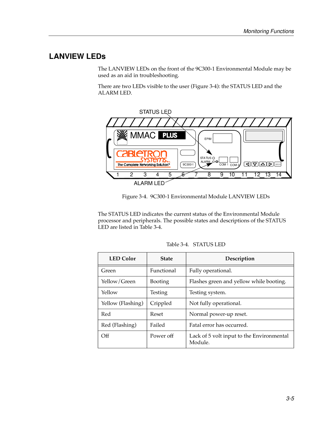
The LANVIEW LEDs on the front of the
There are two LEDs visible to the user (Figure
ALARM LED.
STATUS LED
| MMAC |
|
|
|
| EPIM |
|
|
|
|
|
| |
|
|
|
|
|
|
| STATUS |
|
|
|
|
|
|
|
|
|
|
|
| ALARM | COM 1 | COM 2 |
|
|
|
| |
|
|
|
|
|
|
|
|
|
| ENT ER | |||
|
|
|
|
|
|
|
|
|
|
| |||
1 | 2 | 3 | 4 | 5 | 6 | 7 | 8 | 9 | 10 | 11 | 12 | 13 | 14 |
ALARM LED
Figure 3-4. 9C300-1 Environmental Module LANVIEW LEDs
The STATUS LED indicates the current status of the Environmental Module processor and peripherals. The possible states and descriptions of the STATUS LED are listed in Table 3-4.
Table
LED Color | State | Description |
|
|
|
|
|
|
Green | Functional | Fully operational. |
|
|
|
Yellow/Green | Booting | Flashes green and yellow while booting. |
|
|
|
Yellow | Testing | Testing system. |
|
|
|
Yellow (Flashing) | Crippled | Not fully operational. |
|
|
|
Red | Reset | Normal |
|
|
|
Red (Flashing) | Failed | Fatal error has occurred. |
|
|
|
Off | Power off | Lack of 5 volt input to the Environmental |
|
| Module. |
|
|
|
